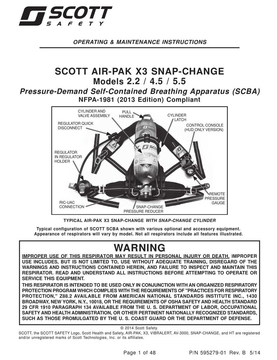
Proper maintenance and understanding of the individual components of breathing protection devices are essential for ensuring their efficiency and safety. The system is made up of various intricate elements that work together to provide reliable performance in hazardous environments. To ensure the longevity and functionality of the equipment, it’s important to have a clear understanding of each piece and how they interact with one another.
Identifying each component and its role within the assembly helps users quickly identify any issues that may arise. Visual representation of these components allows for easier troubleshooting and repair, promoting confidence in the equipment’s use in critical situations. An in-depth knowledge of the system helps users maintain the device with precision and enhances their ability to respond to emergencies effectively.
Familiarizing yourself with the structure also aids in ensuring proper functionality over time. Whether for routine checks or emergency repairs, knowing how the components fit together makes a significant difference in performance and safety during use.
Understanding Breathing Apparatus Components
The functionality of any breathing protection system relies on the coordination of its individual components. Each piece serves a specific function to ensure the safety of the user, especially in high-risk environments. Understanding how these elements interact and contribute to the overall system is vital for optimal performance and effective troubleshooting.
Key Elements of the Breathing Assembly
The main components of the breathing apparatus system include the air supply mechanism, pressure control system, and the interface that connects with the user. Each of these elements plays a distinct role in maintaining airflow, pressure stability, and user comfort during operation. The airflow mechanism ensures that a continuous supply of breathable air is provided, while the pressure control system regulates the flow to prevent sudden surges that could affect the wearer. The user interface connects the device to the individual, ensuring a secure fit and comfort.
Maintenance and Inspection
Regular inspection and maintenance of these components are crucial for long-term reliability. Routine checks allow users to identify wear and tear, ensuring that each part is functioning properly. It’s important to focus on any seals, connections, and pressure settings to prevent leaks and ensure the system operates as expected in emergency situations. An understanding of the mechanism allows for precise maintenance and early detection of potential issues.
Importance of Breathing Apparatus Maintenance
Maintaining the individual components of any protective respiratory system is essential for ensuring it functions properly in critical situations. Regular upkeep not only enhances the longevity of the equipment but also ensures that it delivers reliable performance when most needed. Ignoring maintenance can lead to failures that compromise the user’s safety, especially in high-risk environments.
Routine inspections help detect minor issues before they develop into major malfunctions. Components such as seals, air supply valves, and pressure regulators are subject to wear and tear, which can result in leaks or improper air flow. By identifying and addressing these problems early, users can prevent hazardous situations and ensure the system remains operational. Regular checks also help maintain the comfort and safety of the individual by keeping the device properly calibrated.
How to Read the Breathing Apparatus Schematic
Understanding the schematic of a breathing protection system is essential for effective maintenance and troubleshooting. A well-constructed schematic provides a visual representation of the components and their relationships within the system. By learning how to interpret these illustrations, users can quickly identify where each part fits and understand how they work together to ensure proper functionality.
Interpreting the Symbols and Connections
Each component in the schematic is represented by specific symbols that denote its function and location within the system. For example, air supply lines are usually indicated by solid lines, while valves and pressure controls are shown with unique icons. Understanding these symbols helps the user follow the flow of air and pressure through the system, identifying potential issues that could affect performance.
Following the Flow of Air and Pressure
The most important aspect of reading the schematic is tracing how air moves through the system. The direction of airflow is often indicated with arrows, helping users understand how each component influences the overall operation. By following this path, users can detect blockages, leaks, or malfunctioning parts that disrupt the normal functioning of the device. Understanding this flow is crucial for both routine checks and emergency repairs.