When maintaining or repairing any appliance, having a clear understanding of its internal structure is essential. A thorough examination of each component allows for better troubleshooting and efficient repairs. This knowledge is particularly useful when dealing with complex models, where every part plays a crucial role in the machine’s operation.
In this guide, we will explore the key elements that make up a GE model, helping you navigate through its components. Knowing where each piece fits and how it contributes to the overall functionality can save both time and money when addressing issues.
Proper identification and understanding of these essential parts ensures you can take effective action when something goes wrong. Whether it’s a minor malfunction or a more serious problem, a detailed look at the system will make the repair process more manageable.
Understanding Ge Quiet Power 3 Components

Each appliance consists of various elements that work together to ensure proper functionality. Recognizing how these individual pieces interact helps in both operating and maintaining the unit. Whether you’re aiming to replace a malfunctioning component or simply want to familiarize yourself with its construction, knowing each section’s role is essential for smooth performance.
The GE model is built with several key mechanisms that contribute to its efficiency. Understanding how each section functions allows you to troubleshoot more effectively and ensures that repairs are made with precision. Familiarity with the internal workings makes it easier to detect potential problems before they escalate into major issues.
From the motor and filtration system to the control mechanisms, every piece has a specific purpose in the operation of the machine. By examining these elements, you can gain valuable insights into the appliance’s overall design and identify which areas require attention when maintenance is necessary.
How to Read the Parts Diagram
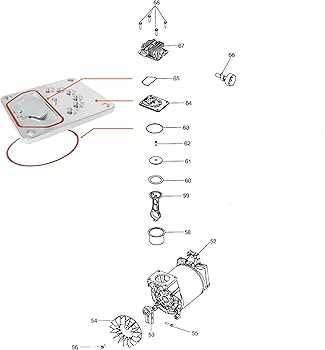
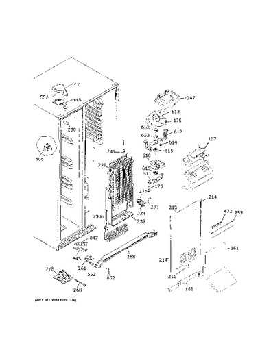
Understanding the layout of an appliance is crucial when performing maintenance or repairs. A well-structured visual representation can provide a detailed overview of the internal components and their relationships. To effectively use such diagrams, it’s important to know how to interpret each section and symbol accurately, which will guide you in identifying and addressing issues.
Breaking Down the Symbols and Labels

Each component in the illustration is labeled for easy identification. Symbols represent different parts of the appliance, and each is associated with a reference number or code. These codes can be cross-referenced with the appliance manual to identify the exact part you’re dealing with. Familiarizing yourself with these symbols ensures that you can locate and address the right areas quickly.
Following the Assembly Sequence
The layout typically shows the components in a logical order, demonstrating how they fit together within the unit. By following the sequence from start to finish, you gain a better understanding of how each element interacts with others. This can be particularly useful when you need to remove or replace a part, as it provides a clear roadmap for disassembly and reassembly.
Common Issues and Parts Identification
When an appliance experiences malfunctions, identifying the root cause is key to finding the right solution. A thorough understanding of the machine’s internal components can help you pinpoint the source of the issue. Recognizing the signs of wear or failure in specific sections can save time and lead to more efficient repairs.
Frequent Malfunctions and Their Causes
One common issue is poor performance or reduced efficiency, which can often be traced back to a clogged filtration system or a faulty motor. Similarly, water leakage could indicate problems with seals or the pump assembly. Knowing how each component functions and where failures are likely to occur helps in narrowing down the potential problem areas.
Identifying Specific Components for Replacement
Once the issue is identified, it’s important to accurately locate the faulty part for replacement. In many cases, components are marked with numbers or reference codes that make identification straightforward. Understanding the layout and knowing how to match these identifiers to the corresponding parts in the manual ensures a precise and quick fix.