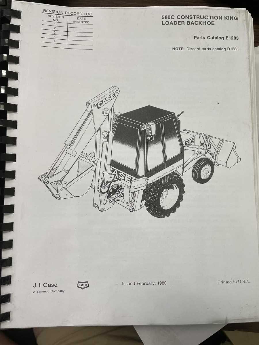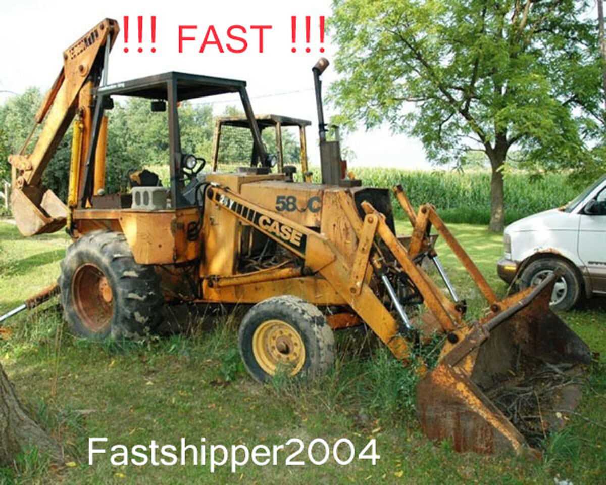
Proper maintenance and efficient operation of construction machinery require a deep understanding of its internal structure. Knowing the layout of all key elements allows operators and technicians to quickly identify parts, diagnose issues, and perform repairs when necessary.
In this section, we will explore the essential components of construction vehicles, focusing on their arrangement and how to interpret detailed technical drawings. These illustrations provide a clear view of each element’s role within the system and help in troubleshooting and optimizing machine performance.
By grasping the organization of the vehicle’s system, operators gain a significant advantage, ensuring better upkeep and minimizing downtime during work. Familiarity with this information also contributes to a longer lifespan for the machine.
Understanding the Construction Vehicle Layout
A comprehensive understanding of a construction vehicle’s layout is crucial for efficient operation and maintenance. By familiarizing oneself with the key structural elements, operators can quickly locate parts and identify potential issues. This knowledge enhances the troubleshooting process and ensures smoother workflows, reducing downtime and improving overall productivity.
The layout typically includes various systems and components such as hydraulic mechanisms, engine sections, and stabilizers, each serving a specific purpose. Recognizing how these elements interconnect and function together allows for more precise repairs and maintenance practices. Proper familiarity with the vehicle’s structure is also essential for maximizing its lifespan and performance on the job site.
Key Components of the Construction Vehicle
To fully understand the operation and functionality of heavy machinery, it’s essential to familiarize oneself with the core components that make up the system. Each part plays a crucial role in ensuring the vehicle performs at its best, whether it’s for digging, lifting, or transporting materials. Understanding how these elements interact with one another helps improve maintenance practices and troubleshooting efficiency.
Hydraulic System

The hydraulic system is the heart of many construction vehicles, enabling powerful movement and lifting capabilities. It controls the machine’s arms, boom, and other key functions by using pressurized fluid. The efficiency of this system is vital for smooth operation and ensuring that heavy loads can be handled without issue.
Engine and Transmission
The engine and transmission are the power sources of the vehicle, responsible for generating movement and converting energy into mechanical action. A properly functioning engine ensures the vehicle can operate under demanding conditions, while the transmission helps control speed and torque, facilitating smooth transitions and optimal performance on various terrains.
How to Read the Technical Layout
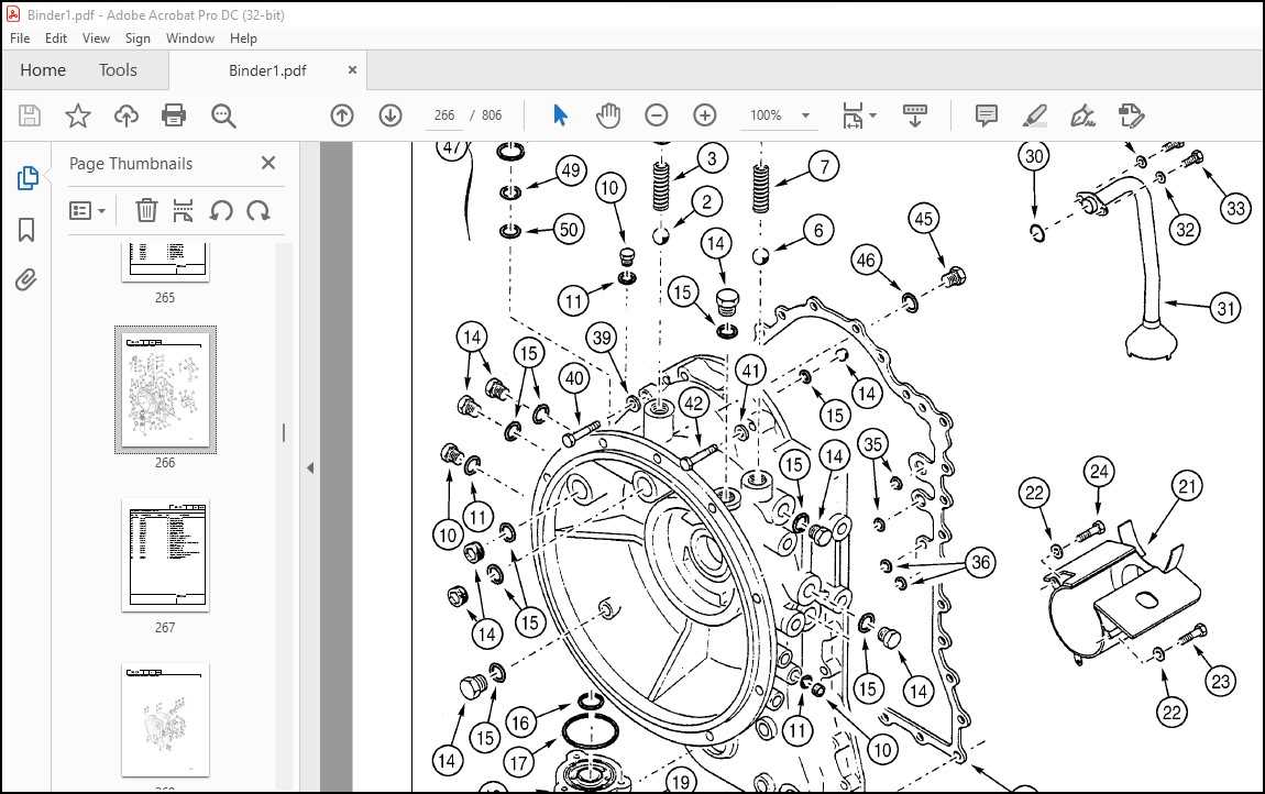
Understanding technical illustrations is key to effective equipment maintenance and repair. These visual guides provide a detailed view of each component and its placement within the machine. By learning to read these layouts, technicians can identify parts, understand their functions, and carry out repairs or upgrades with greater accuracy and efficiency.
Identifying Components

Each symbol or number in the layout represents a specific part of the machine. By referring to the corresponding legend or list, users can match these visual cues to the actual components. Familiarizing oneself with common symbols used in these diagrams helps streamline the process of identifying which parts require attention or replacement.
Interpreting Connections and Flow
In addition to parts, the layout also shows how different systems are connected. Arrows and lines indicate fluid or power flow, helping users understand the interactions between components. Recognizing these connections ensures that all parts work together as intended and helps in diagnosing issues related to power or fluid circulation.