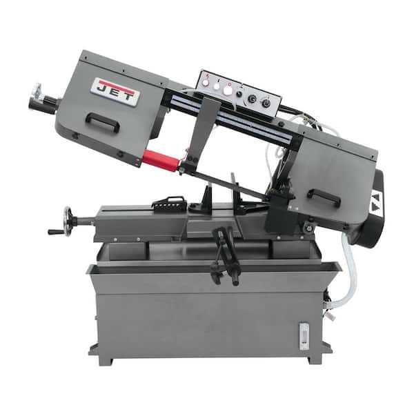
When working with complex machinery, it’s essential to familiarize yourself with its internal structure and various components. Recognizing how each part functions can significantly improve your ability to troubleshoot and maintain the equipment. This knowledge is not only vital for repairs but also helps enhance the performance and longevity of your tools.
Proper maintenance begins with understanding the different elements of the machine, from the main framework to the smallest accessories. Each part plays a crucial role in ensuring the tool operates smoothly. Whether you’re a professional or a hobbyist, knowing where every component fits and how it contributes to the overall system is key to effective usage.
Detailed illustrations can be immensely helpful for visualizing these elements and learning their interconnections. They serve as guides for both identifying specific pieces and understanding their precise function. Whether you’re dealing with wear and tear or upgrading your machine, a clear representation of the layout can make a big difference in your repair and maintenance efforts.
Understanding the Machine Components
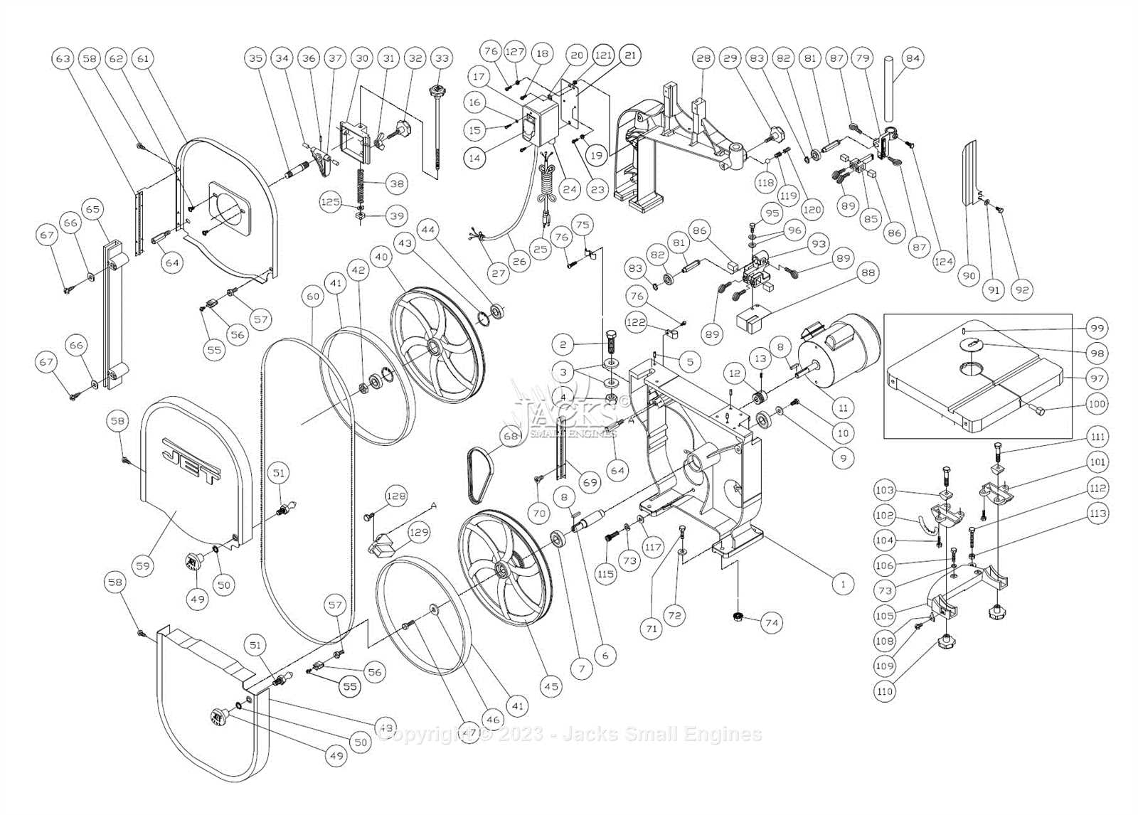
To ensure optimal operation and longevity of any tool, it is crucial to comprehend the role of each individual element. Familiarizing yourself with the structure of the equipment, from its primary framework to smaller accessories, enables more effective handling and maintenance. Each component has a specific function that contributes to the overall efficiency of the system, and knowing how they work together is essential for keeping the machine in top condition.
Main Structural Elements
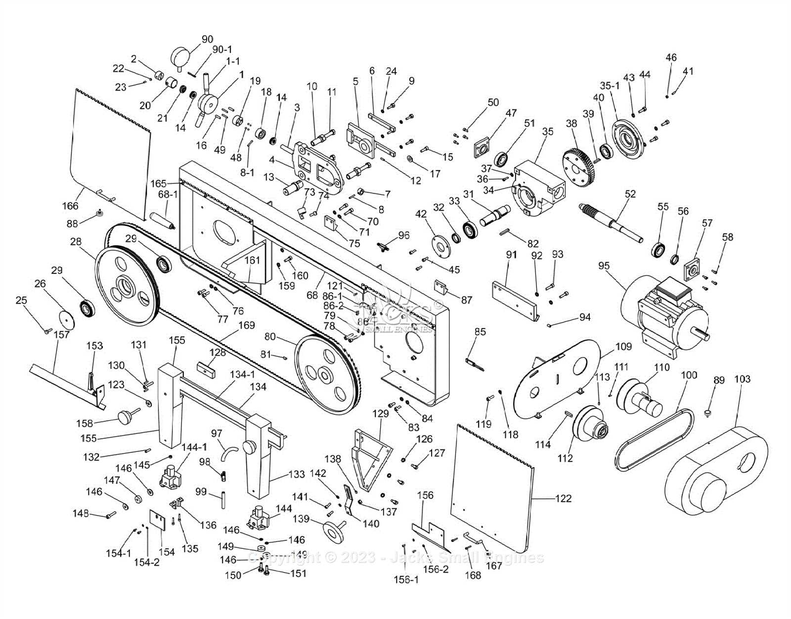
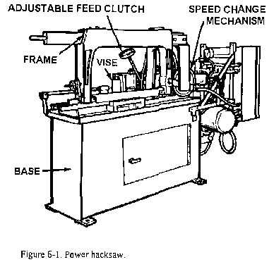
The core elements of the machine provide the foundation for its function. These parts are responsible for the tool’s stability and alignment during use. They ensure that all other components operate smoothly and within their intended range. Recognizing these key structures is the first step in understanding how the entire system works.
Additional Functional Components
Smaller components, though often overlooked, play an equally vital role in the machine’s operation. These parts control movement, precision, and various adjustments that improve performance. By understanding how each functional piece interacts with the rest, users can prevent common issues such as misalignment or premature wear.
Accurate maintenance relies on being able to identify these components and understand their purpose within the system. Recognizing the connections between parts helps streamline troubleshooting and repairs, ensuring that the machine continues to function optimally for years.
How to Read a Machine Layout
Interpreting a visual representation of a machine can significantly enhance your understanding of its structure and functionality. These illustrations provide a clear overview of how various elements are arranged and connected within the system. By examining the layout, you can quickly identify individual components and their relationships, which is crucial for effective troubleshooting and maintenance.
Key Symbols and Labels
Most diagrams use specific symbols and labels to represent different components. Understanding these visual cues is essential for accurate interpretation. For example, shapes and lines often indicate the type of part, while labels provide additional information such as model numbers or functional details. Familiarizing yourself with these symbols will make reading the layout much easier.
Locating and Identifying Components
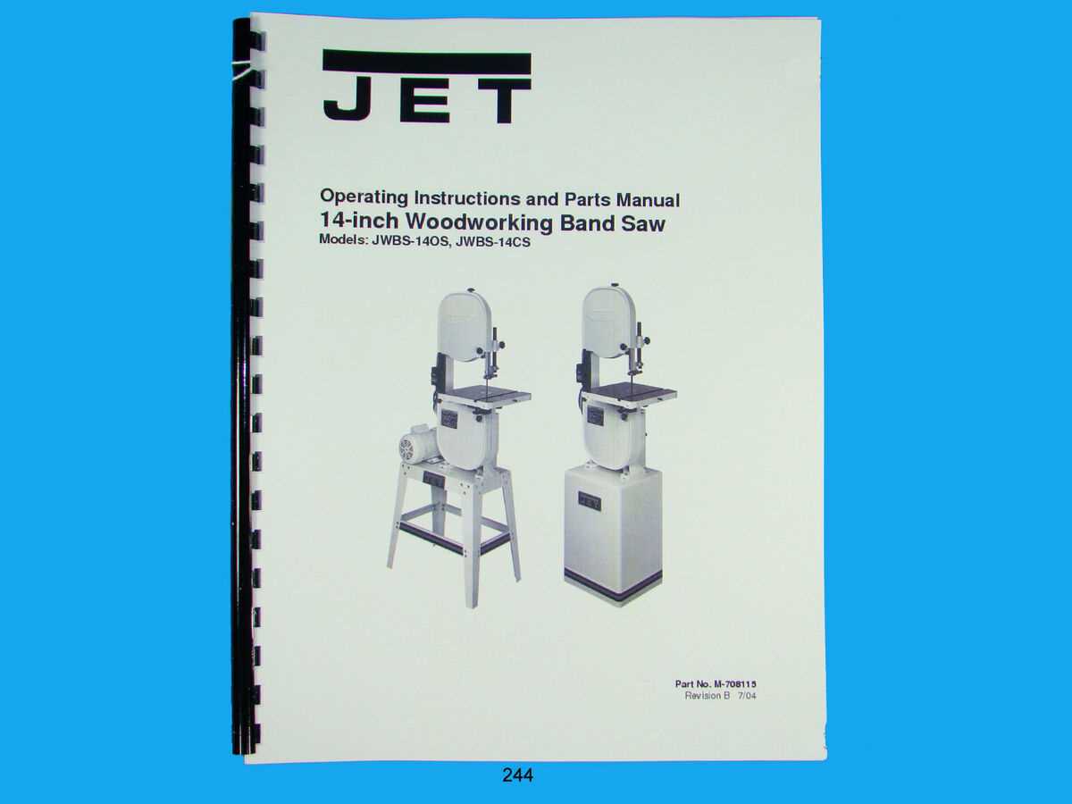
Once you’re familiar with the key symbols, the next step is to identify the components within the diagram. Carefully trace each section and look for connections that show how parts interact with each other. Pay attention to any annotations that describe the role or function of specific elements. This knowledge is crucial for making repairs or adjustments with precision.
Clear diagrams serve as invaluable guides, especially when you need to identify malfunctioning elements or perform regular maintenance. Being able to read these layouts effectively will help you take a more informed approach to machine care, preventing unnecessary issues and prolonging the life of the equipment.
Common Machine Components and Functions
Every tool contains essential elements that serve distinct functions, all contributing to the machine’s overall efficiency. Understanding these components allows users to maximize the tool’s potential, whether for regular operation or in times of repair. Each piece works in tandem with others to ensure precision and durability, making it critical to know the role of each part within the system.
Main Structural Elements
The core structure of the machine provides the necessary stability for all other components to function correctly. This includes the frame, which supports the entire system, and the guide mechanisms that ensure smooth operation. These elements are crucial for maintaining alignment and precision during use. Without them, the tool would lose accuracy and the ability to perform its intended tasks.
Functional Components
Additional functional pieces are responsible for the tool’s operational capabilities. These parts control movement, provide tension, and allow for adjustments during use. Examples include the motor, drive belt, and tensioning system, all of which contribute to the machine’s performance. Knowing the role of each functional component is vital for troubleshooting common issues, such as speed inconsistencies or alignment problems.
Regular inspection of these elements ensures they remain in optimal condition, helping to avoid unnecessary downtime. Understanding the purpose of each functional component not only aids in machine care but also allows users to make informed decisions about maintenance and repairs.