When operating complex construction equipment, knowing the various components and their functions is essential for efficient use and proper maintenance. This knowledge allows for quicker troubleshooting, easier repairs, and better overall performance.
Understanding the internal structure of machines plays a crucial role in their longevity and effectiveness. Recognizing how each element works together ensures smoother operations and prevents unexpected breakdowns.
Visual guides are often the most effective way to familiarize oneself with the equipment. These references break down intricate designs, allowing for easier identification and management of each segment, ensuring that operators can maintain peak performance at all times.
Understanding the Heavy Equipment Structure

Understanding the internal organization of construction machinery is crucial for anyone involved in maintenance, operation, or repairs. Each machine consists of several interconnected systems, each with a specific role that contributes to the overall functionality. Recognizing how these components interact ensures that operators can manage the equipment more effectively and address issues promptly.
The core framework serves as the foundation of the equipment, providing structural support to all other systems. It holds the engine, hydraulic components, and lifting mechanisms in place, making it essential for the machine’s stability and performance.
Hydraulic systems are integral to the operation of various elements, such as the lifting arm and digging tools. These systems rely on fluid pressure to perform tasks that require significant force, enabling efficient excavation and material handling.
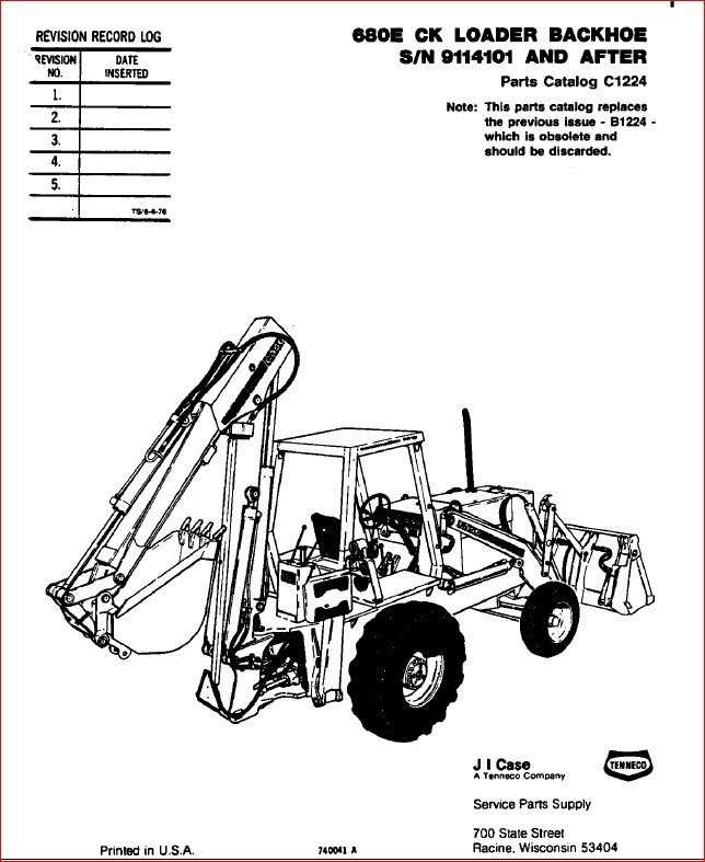
Key Components of a Backhoe Machine

Every heavy-duty construction vehicle is a complex system of interconnected elements that work together to achieve various tasks efficiently. These machines are designed to dig, move, and lift large quantities of material. Each section of the machine plays a crucial role in ensuring proper functionality and performance under demanding conditions.
Engine serves as the heart of the machine, providing the power required to operate various functions. It is essential for maintaining performance and ensuring that all the moving parts receive enough energy to function smoothly.
Hydraulic System is a key feature in these machines, controlling the movement and force applied by different components. It enables precise control over the boom, arm, and bucket, allowing for efficient operation in various environments.
Frame acts as the core structure that holds all other elements in place. It must be strong enough to withstand the heavy loads and harsh conditions that come with excavation work.
Bucket is the primary tool for digging and scooping material. Its design can vary depending on the intended purpose, such as trenching, lifting, or loading. The capacity and shape are tailored for maximum efficiency in specific tasks.
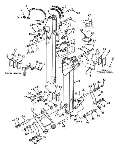
Boom and Arm work together to extend the machine’s reach and provide the necessary lifting force for various operations. The boom allows the operator to position the arm and bucket accurately, providing versatility for different job types.
Cab is where the operator controls the machine. It is designed for comfort and safety, ensuring the user has a clear view and easy access to all necessary controls.
Each of these elements contributes to the overall capability of the machine, ensuring efficiency and versatility in construction, digging, and lifting tasks.
How to Identify Backhoe Parts Easily

When dealing with heavy machinery, recognizing individual components is crucial for maintenance and repairs. Understanding the function and appearance of each element allows for better decision-making during operation and troubleshooting. Knowing where each part is located and how it interacts with the others can make a significant difference in efficiency.
1. Visual Inspection
The most straightforward method is a simple visual inspection. Each section of the machine has distinctive features that can be identified by their shape and function. Pay attention to the following areas:
- Arm and Boom: These are typically large, long components designed for digging and lifting. The boom is the main structure that extends from the body, while the arm is connected to the bucket.
- Bucket: This is the attachment at the end of the arm used for scooping and lifting material. Its size and shape may vary based on the specific task.
- Hydraulic Cylinders: Often visible along the boom and arm, these cylinders control the movement of the machine’s various elements through fluid pressure.
- Cab: This is the enclosed area where the operator sits. It’s essential for controlling the machine’s functions safely.
2. Consult the Manual
Another effective way to identify various elements is by referring to the user manual or technical guide. These documents often provide detailed information about each component’s name, function, and location. For an accurate identification, refer to:
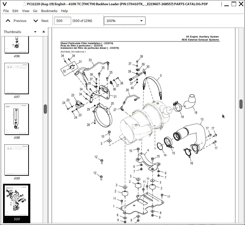
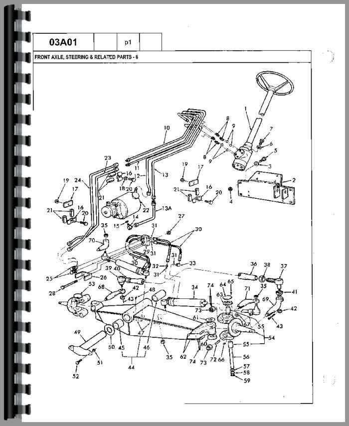
- Component Labeling: Manuals often include images with labels or annotations indicating the position of key elements.
- Part Numbers: The manual may contain part numbers that make identifying specific elements easier when ordering replacements or accessories.
By combining visual cues and references to technical documents, recognizing individual machine components becomes an intuitive process that helps ensure the longevity and effectiveness of the equipment.