In any electrical system, various essential elements work together to ensure smooth operation and optimal performance. These components, often depicted in schematics, play specific roles in converting energy, managing flow, and maintaining stability. Understanding how each piece contributes to the overall functionality is crucial for both installation and troubleshooting.
Each system is designed with a series of interconnected elements, where the interaction of components directly influences the efficiency and reliability of the setup. By examining how these parts are arranged and function together, one can gain a deeper insight into the mechanics of energy transfer and management.
Recognizing the different components and their individual functions is essential for diagnosing issues, performing maintenance, or even upgrading systems. This knowledge not only helps in understanding the structure but also enables better control over the device’s performance and longevity.
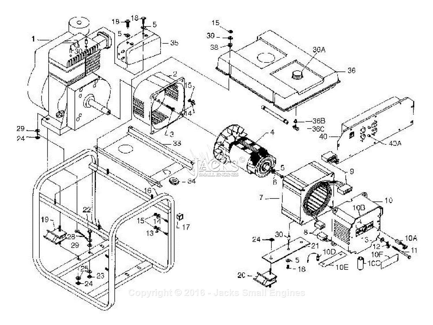
Key Components of a Generator Diagram
Every electrical system involves a range of crucial elements that work in tandem to convert energy and maintain stability. These components can be identified through schematic representations, where each element’s role is outlined clearly. Understanding how these different elements fit together allows for a comprehensive view of the entire setup and its functionality.
Energy Conversion Elements
At the heart of any system lies the mechanism responsible for transforming one form of energy into another. These core elements serve to initiate the process of energy transfer, ensuring that the system is capable of generating or harnessing power efficiently. Their design is essential to maintaining consistent output and meeting the required operational standards.
Control and Regulation Components
In addition to the conversion mechanism, a series of control and regulation components are necessary to maintain proper functioning. These parts monitor and adjust the flow of energy, ensuring that the system operates within safe parameters. Proper control mechanisms are vital for preventing overloads and ensuring optimal performance throughout the system’s lifespan.
How Generator Parts Work Together

In any electrical system, the various components must interact harmoniously to ensure proper functionality. Each element has a specific role, and when combined, they work to achieve the desired output. The coordination of these elements is critical for maintaining efficiency, stability, and safety within the entire system.
Coordinating Energy Flow

The primary function of the interconnected components is to manage and direct the flow of energy. Each unit is designed to perform a specific task, whether it be converting energy, regulating output, or ensuring proper connections. Through this seamless integration, the system can operate effectively and meet the required energy demands.
Ensuring System Stability
In addition to energy conversion, the components also play a key role in ensuring that the system remains balanced. Monitoring and adjusting parameters such as voltage, current, and power are essential to preventing malfunctions. The interaction between the elements helps to keep the system running smoothly while safeguarding it from potential issues like overloads or instability.
Identifying Generator Parts in Diagrams
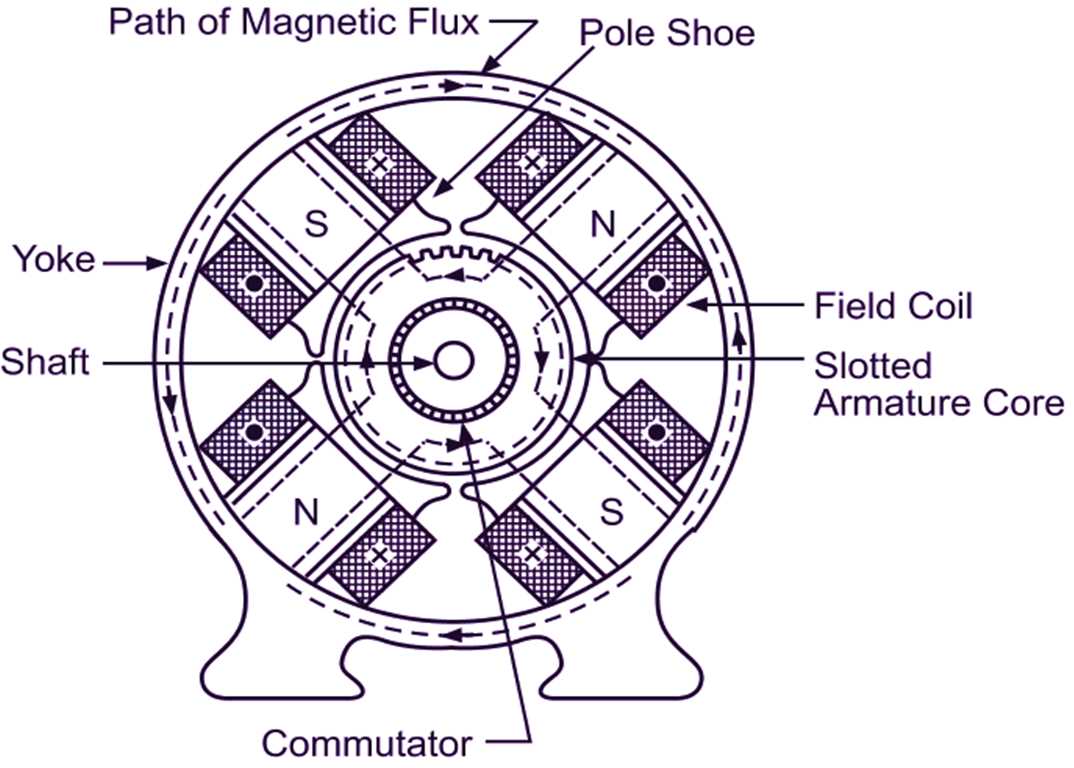
When working with electrical schematics, it’s essential to be able to recognize the various elements and their respective functions. Each component is represented by a specific symbol or shape, allowing for quick identification and understanding. Knowing how to interpret these representations is key to diagnosing issues, performing maintenance, or designing efficient systems.
Recognizing Symbolic Representations
In most technical illustrations, different components are shown through standardized symbols that denote their purpose and connection within the system. These visual representations allow engineers and technicians to easily differentiate between parts, such as those responsible for energy conversion or regulation. Understanding these symbols is crucial for accurate interpretation of the schematic.
Tracing Connections Between Units
Beyond symbols, the lines and connections between elements are just as important for understanding how the system functions. These connections represent electrical paths that enable energy flow between components. Identifying how each unit is linked to the others helps in recognizing how the entire system works as a whole and where potential issues may arise.