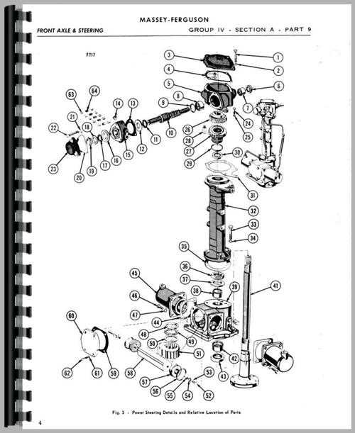
Understanding the critical components of a tractor’s handling system is essential for proper maintenance and efficient operation. This section covers everything you need to know about the mechanism responsible for controlling the direction of your machinery. By familiarizing yourself with each element, you can troubleshoot issues and ensure long-term reliability.
In this guide, we will explore the individual components that make up the system, from the central control unit to the smaller interconnected parts. You’ll learn how to identify each element, its role in the overall structure, and the best ways to maintain them for peak performance.
For those who are looking to repair or replace specific elements, this guide provides a clear path to understanding how everything fits together. With a comprehensive overview, you will be equipped to handle any challenges that arise with the handling system of your equipment.
Understanding Tractor Control System
The control system responsible for directing the movement of agricultural machinery is a crucial aspect of its overall functionality. It ensures that the vehicle can be maneuvered efficiently, allowing the operator to navigate through fields or tight spaces with ease. Without a well-functioning mechanism, handling becomes difficult, leading to potential safety issues and decreased productivity.
This system is made up of various elements that work together to provide smooth and precise direction control. Each component, from the central unit to the smaller interconnected mechanisms, plays a vital role in ensuring accurate movement. Understanding how these parts interact helps in diagnosing issues and improving the machine’s overall performance.
Regular inspection and maintenance of this system are essential for long-term reliability. By keeping the control elements in optimal condition, you can avoid costly repairs and ensure that the equipment remains operational in the most demanding conditions.
Key Components of Steering Mechanism
The direction control system is composed of several essential elements that work in harmony to ensure smooth handling and precise movement. Each of these components has a unique function, but together they create a cohesive mechanism that allows for efficient navigation and maneuverability. Understanding each element is important for proper maintenance and troubleshooting.
Central Control Unit
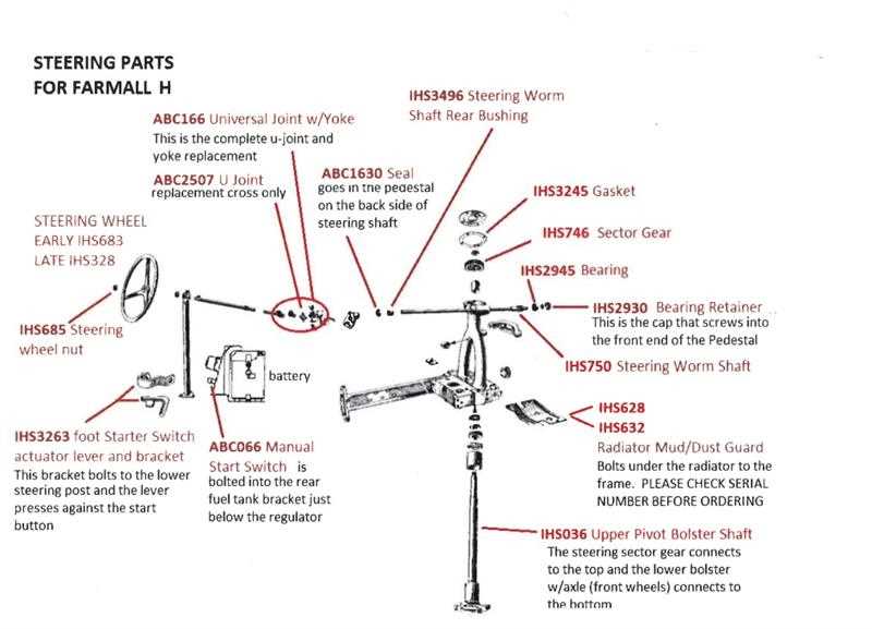
The central control unit is the heart of the entire mechanism. It allows the operator to influence the direction of the machine by transmitting signals to the other components. This unit is responsible for providing the necessary force to initiate the desired movement and maintain stability throughout the operation.
Linkage and Connecting Mechanisms
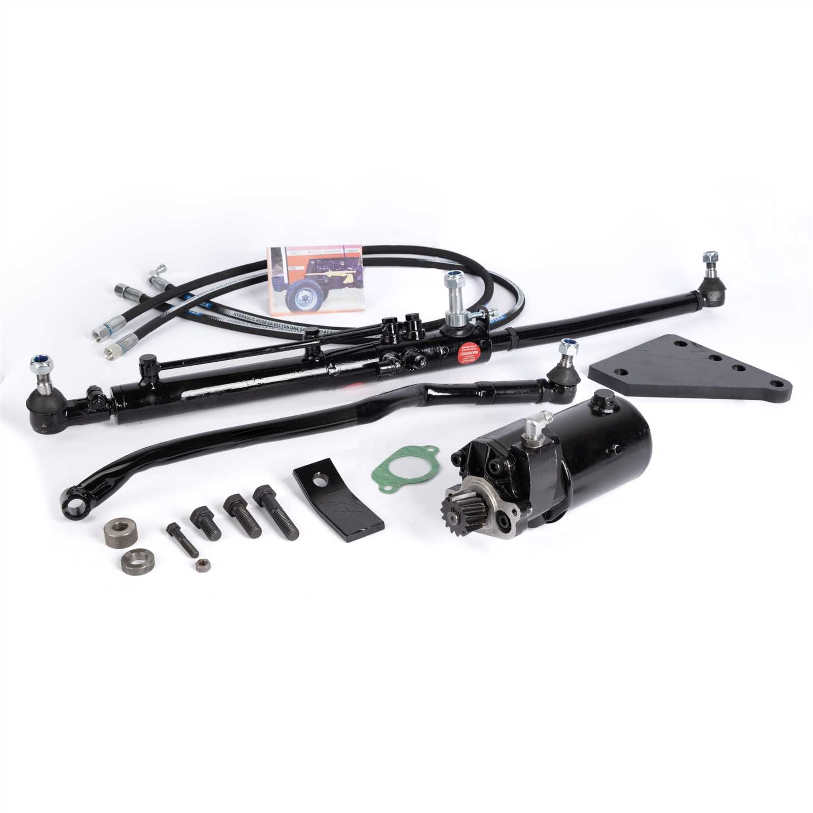
Connecting parts, such as linkages and rods, form the critical connections between the central unit and the wheels. These elements ensure that the input from the control unit is accurately transferred to the wheels, providing the desired turning radius and responsiveness. They must be regularly inspected to prevent wear and ensure proper function.
How to Read the Control System Layout
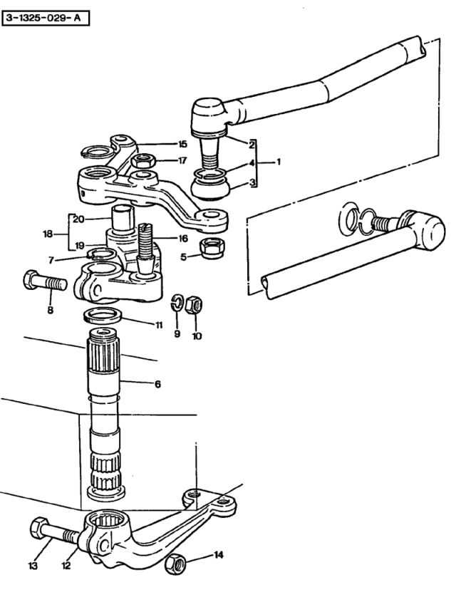
Understanding how to interpret the layout of the control system is a key skill for anyone performing maintenance or repairs. The layout provides a visual representation of how the components are arranged and interact with one another. By becoming familiar with this diagram, you can quickly identify specific elements and troubleshoot problems with greater efficiency.
Identifying the Key Elements
Each symbol on the layout corresponds to a particular component or connection within the system. These symbols are standardized, making it easier to identify parts and their functions. Understanding each symbol’s meaning is essential before attempting any repairs or replacements. Focus on identifying the central control unit, connecting rods, and any other moving parts that are crucial to the system’s operation.
Understanding Connections and Flow
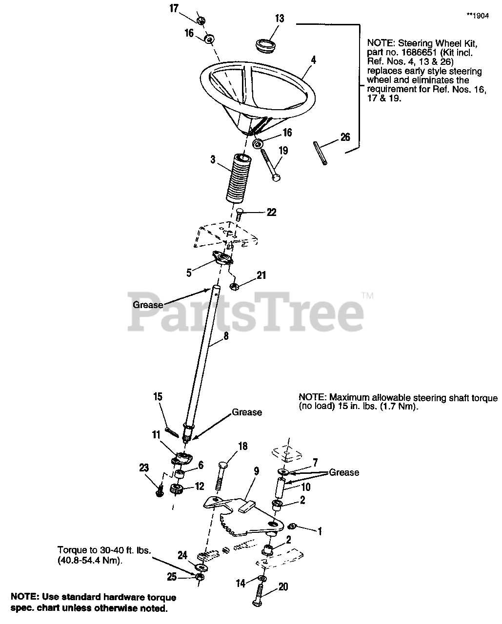
The layout also shows how the elements are interconnected and how the flow of motion is transferred from one component to another. Pay attention to the lines and arrows that indicate the direction of force or movement. This will help you visualize how input is transmitted to achieve the desired output, whether it’s turning or adjusting the vehicle’s direction.