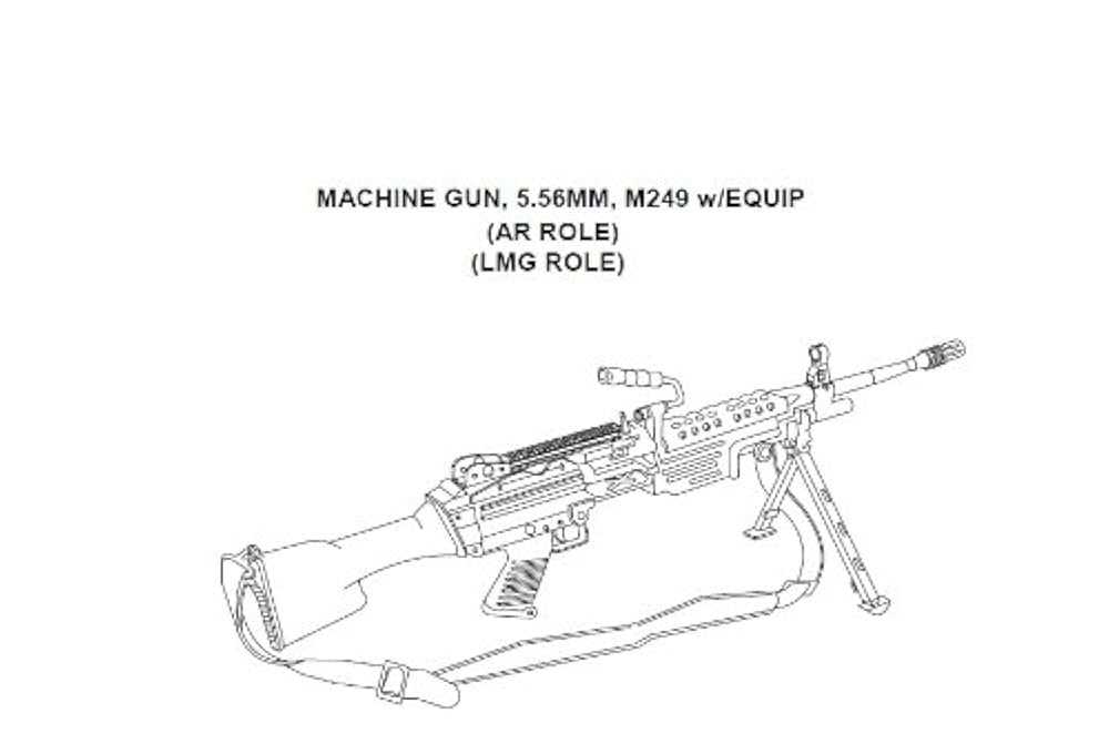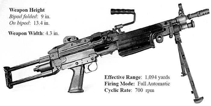
Every complex weapon system is made up of several interconnected elements that work together to ensure optimal performance. Knowing how each piece contributes to the overall function can greatly enhance maintenance and repair efforts. Whether for military, law enforcement, or enthusiast purposes, understanding the construction of such firearms is crucial for proper handling and longevity.
Breaking down the structure of these firearms allows users to identify essential components, troubleshoot malfunctions, and perform necessary repairs efficiently. By gaining a deep understanding of how the individual pieces interact, one can ensure the firearm remains reliable and effective in various operational conditions.
In this guide, we will examine the key elements of this machine, providing insights into how they fit together, their specific roles, and tips for maintenance. Mastering the mechanics behind it will give users a significant advantage in both operational efficiency and upkeep.
Understanding the M249 Components
Every firearm consists of various crucial elements that work in unison to ensure reliable operation. The complexity of such a system requires a deep understanding of how each individual part functions and contributes to the overall effectiveness. Proper knowledge of these components helps users maintain, repair, and optimize performance in any situation.
Core Functional Elements
The heart of any machine gun lies in its firing mechanism, trigger system, and feeding mechanism. These systems allow for rapid and continuous firing, providing both firepower and control. Understanding how each piece works within these systems can drastically improve both the operational readiness and longevity of the firearm.
Maintenance and Troubleshooting

Routine maintenance is essential for the proper functioning of a firearm. Knowing how to break down the key components and perform regular checks ensures that the weapon remains reliable under various conditions. Common issues, such as feeding malfunctions or misfires, can often be traced back to specific components, making a solid understanding of each part vital for effective troubleshooting.
How to Read an M249 Parts Diagram
Understanding how to interpret technical schematics is a valuable skill when working with complex mechanical systems. These visual representations show how individual elements fit together and function as a whole, making it easier to identify components, their positions, and interconnections. Being able to read such illustrations ensures accurate assembly, disassembly, and maintenance.
Identifying Key Components
Each illustration highlights specific components of the firearm, often labeled with numbers or names. Understanding these labels and their corresponding elements is the first step in decoding the schematic. By recognizing these identifiers, you can quickly locate the necessary parts for maintenance or replacement.
Understanding the Flow and Assembly
These schematics also show the sequence in which parts are assembled or disassembled. Arrows and lines indicate how parts connect, offering a clear visual guide for proper reassembly. Paying attention to the flow can prevent errors and ensure that the system operates as intended after reassembly.
Essential Parts of the M249 Machine Gun
Every firearm is composed of several critical components that enable it to function effectively. These elements serve various purposes, from housing ammunition to controlling the firing mechanism. Recognizing the most essential components and understanding their roles is key to ensuring proper operation and maintenance of the weapon.
The following are some of the key elements that contribute to the functionality of the firearm:
- Receiver: The central housing that contains key mechanisms and connects the different parts of the firearm.
- Barrel: The part through which the ammunition travels when fired, crucial for both accuracy and heat dissipation.
- Feeding Mechanism: A system that loads rounds into the chamber, ensuring continuous fire in automatic mode.
- Trigger Assembly: The mechanism that initiates the firing sequence when pulled.
- Gas Piston: Responsible for using the gas generated by firing to cycle the action and load the next round.
- Bolt Assembly: A critical component that locks the ammunition into the chamber and handles the cycling of spent casings.
- Stock: Provides stability and allows the user to control the weapon during firing.
Understanding each of these components and their interactions ensures that the system operates smoothly and effectively, allowing users to perform proper maintenance, troubleshooting, and repairs when needed.