When maintaining or repairing any power tool, understanding its individual components and how they fit together is essential. This knowledge helps users troubleshoot issues, perform necessary repairs, and keep their equipment in top condition for longer use. Whether you are a DIY enthusiast or a professional, having a detailed visual reference for tool parts can make all the difference.
Proper maintenance ensures that your equipment functions efficiently, preventing costly replacements and extending its lifespan. A comprehensive breakdown of the internal and external parts allows users to identify problem areas quickly and apply the right solutions.
By exploring the breakdown of each element in the tool, you can gain a deeper insight into its overall structure. This guide will walk you through how to interpret and use these visual references to improve the performance and longevity of your device.
Understanding the Tool Assembly Breakdown
To effectively maintain or repair any power tool, it is crucial to grasp the individual components and how they interact with one another. This visual guide helps users identify various elements of the tool’s structure, offering a clear view of how everything fits together. Knowing this information is key to diagnosing issues, ordering replacement parts, and ensuring the tool operates smoothly.
Identifying Key Elements of the Tool
The first step in understanding the breakdown is recognizing the major parts that make up the device. From the housing to internal gears, each component serves a specific function that contributes to the overall performance. Identifying these elements in detail allows users to understand their role in the operation and pinpoint potential issues when the tool isn’t performing as expected.
How to Interpret the Assembly Reference

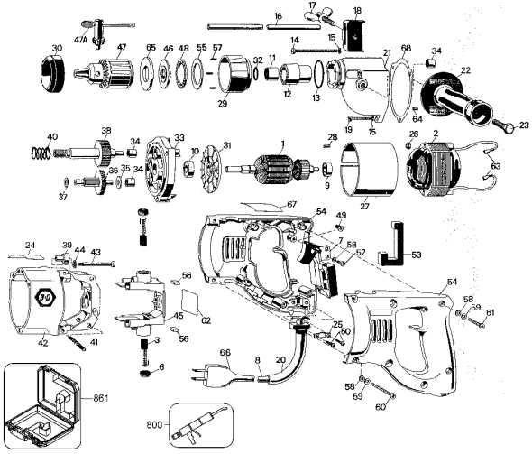
Once familiar with the individual components, the next step is to learn how to read the assembly reference. This reference illustrates how each part connects to others, offering a visual map of the tool’s assembly. By studying this reference, users can easily locate any worn or damaged components and address repairs more efficiently.
Key Components of the Tool

Every power tool consists of a variety of crucial elements that work together to ensure proper functionality. Understanding these primary components is vital for both troubleshooting and performing effective repairs. These key parts are responsible for the tool’s overall performance, and identifying any issues with them can help restore the device to full working order.
Motor and Power Mechanisms
The motor is at the heart of any power tool, converting electrical energy into mechanical power. It drives the key functions of the device, such as rotation or vibration, depending on its design. Alongside the motor, other power mechanisms, including gears and brushes, play an important role in transferring energy to the working parts, ensuring smooth operation and efficiency.
Housing and Safety Features
The outer casing of the tool not only provides protection but also houses various internal components. This protective shell shields users from moving parts while also containing the device’s wiring and motor. Additionally, safety features such as triggers, locks, and shields are essential in preventing accidents and ensuring user safety during operation.
How to Use the Assembly Reference for Repairs
When it comes to repairing a tool, having a clear visual guide of its components can significantly simplify the process. These references provide a detailed breakdown of how each part fits into the larger structure, helping you identify which components need attention. By using this guide effectively, you can troubleshoot problems, find the necessary replacements, and carry out repairs with greater ease.
Identifying Faulty Components
The first step in utilizing the assembly reference is to pinpoint the damaged or worn parts. With a detailed illustration of the tool’s structure, you can trace the specific area where an issue might lie. By comparing the actual condition of your tool with the guide, you’ll quickly see which part requires maintenance or replacement, ensuring minimal downtime.
Ordering Replacements and Assembly
Once the problematic parts are identified, the next step is to order the correct replacements. The reference will help you match the part numbers and details needed for a precise replacement. By ensuring the proper parts are ordered, you can complete the repair efficiently and correctly, restoring the tool’s functionality to its optimal state.