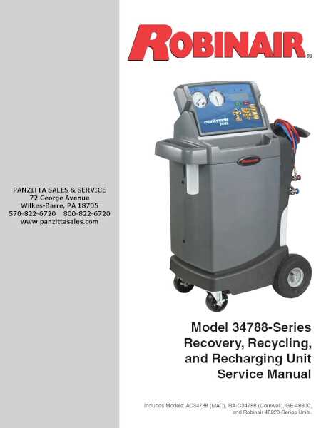
When maintaining or repairing any advanced equipment, it is essential to have a clear understanding of its internal structure and functionality. A comprehensive visual reference can significantly aid in identifying various elements, ensuring smooth operation and efficient troubleshooting.
Efficient maintenance often relies on recognizing individual parts and their roles within the overall system. By studying an organized schematic representation, users can easily pinpoint faulty components or make informed decisions when performing repairs. This guide will walk you through the vital parts of the unit, helping you better understand their positioning and function.
Understanding the layout not only enhances your ability to resolve issues but also ensures that the system continues to operate at optimal performance. Properly interpreting a visual map allows for quicker fixes, extending the lifespan of your equipment and reducing the chances of future malfunctions.
Understanding the Equipment Layout

A clear and detailed visual reference of your device’s internal components is essential for troubleshooting and maintenance. This organized layout allows users to quickly identify each individual part and its role in the overall functioning of the system. By carefully analyzing these illustrations, you can gain a deeper understanding of how each piece interacts within the machinery, ensuring optimal performance and reducing the risk of malfunctions.
Key Features to Identify

When examining the visual guide, there are several critical features to focus on:
- Component Identification: Recognizing the name and location of each element helps in both maintenance and repair tasks.
- Flow Paths: Understanding the movement of fluids or gases between parts ensures that you can pinpoint potential blockages or inefficiencies.
- Connection Points: Identifying how different components are connected can make disassembly or reassembly easier and more efficient.
Utilizing the Visual Guide for Repairs
Once you are familiar with the general layout, the next step is to use this knowledge for practical repairs. A well-documented schematic can guide you through:
- Locating damaged or worn-out parts that need replacement.
- Determining the right tools for disassembling and accessing internal elements.
- Ensuring correct reassembly to maintain the system’s integrity.
Key Components of the Unit

Each system consists of various essential components that work in harmony to ensure optimal functionality. Identifying and understanding these core elements is crucial for effective operation, maintenance, and troubleshooting. The following sections highlight the primary components of the device, providing insight into their role and importance within the overall system.
Critical Mechanical Elements
The mechanical elements are the heart of the system, driving its core functions. These components often include:
- Motors and Drives: Responsible for powering the system’s moving parts, these components must be regularly inspected for wear and proper function.
- Seals and Gaskets: Ensuring no leakage occurs, these elements play a key role in maintaining the system’s pressure and integrity.
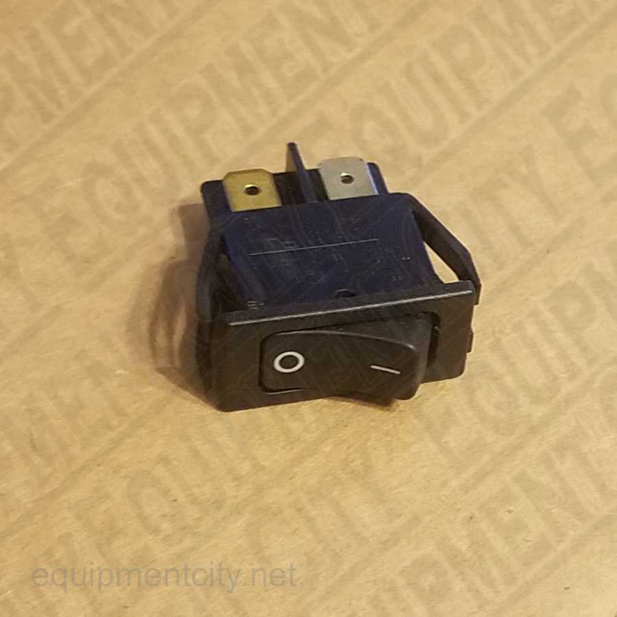
- Switches and Valves: These control the flow of fluids or gases, and must be precisely calibrated to avoid disruptions in the unit’s operation.
Supporting Functional Elements
In addition to the primary mechanical components, supporting elements help enhance performance and facilitate smooth operation. These typically include:
- Heat Exchangers: Vital for maintaining appropriate temperature levels, these components ensure the system does not overheat during use.
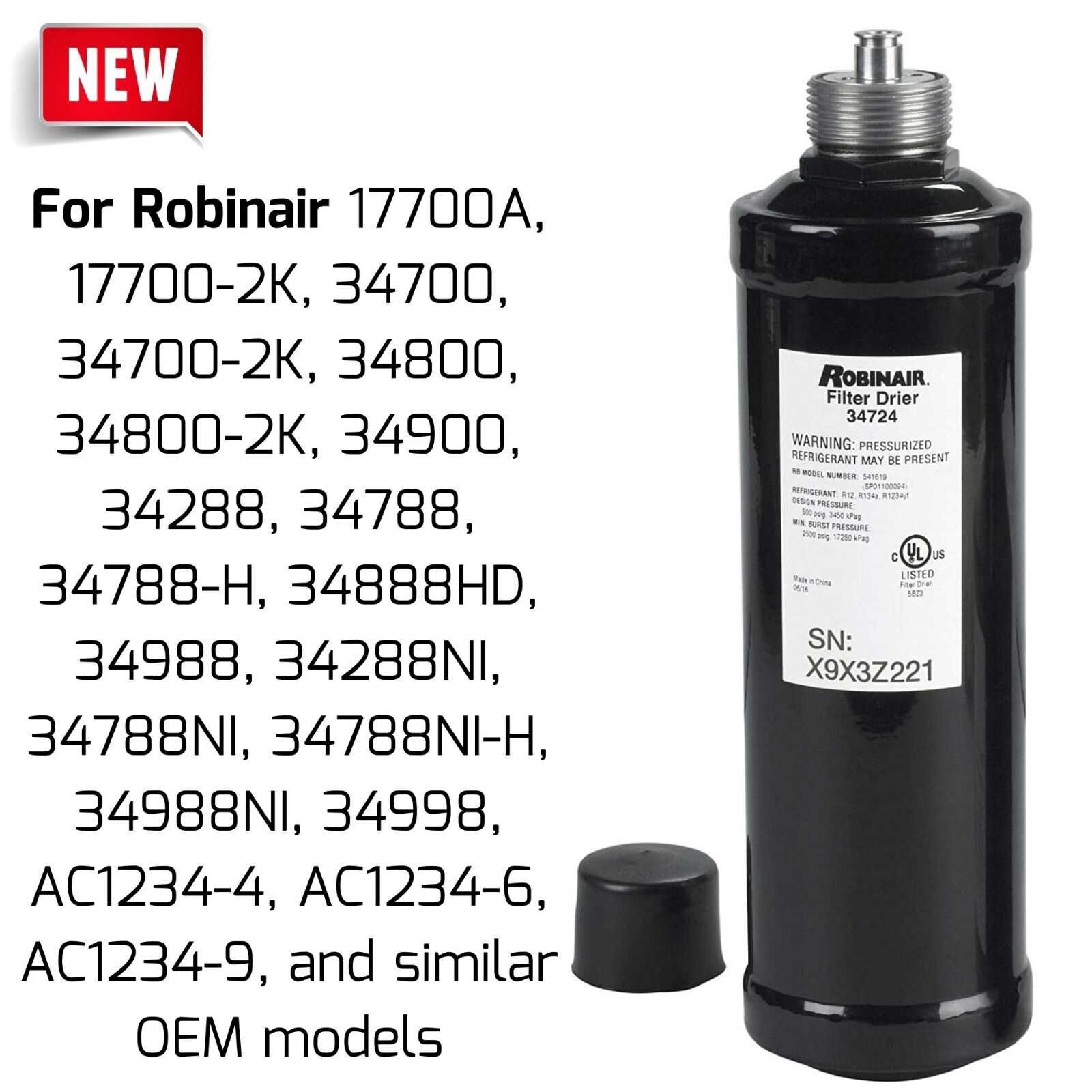
- Filters and Regulators: Protecting sensitive parts, these elements control the cleanliness and pressure of the working fluids.
- Displays and Indicators: Providing real-time feedback, these help the operator monitor and control the system’s status effectively.
How to Use the Visual Guide Effectively
A comprehensive visual guide can be a valuable tool for anyone involved in the repair or maintenance of complex equipment. It provides a clear representation of the system’s structure, helping users locate specific components and understand their interconnections. To make the most out of this reference, it’s essential to approach it with a strategic mindset and focus on key elements.
Start by familiarizing yourself with the overall layout and identifying the major components. Pay attention to the labels and references, which will direct you to the specific areas you need to focus on. Use the guide to pinpoint potential problem areas, trace fluid or gas pathways, and ensure all parts are correctly assembled.
When performing repairs, refer back to the guide to locate exact replacement components, making it easier to access and replace faulty parts. Additionally, the visual guide can be a helpful resource for checking assembly steps, ensuring everything is put back together in the right order and position for optimal performance.