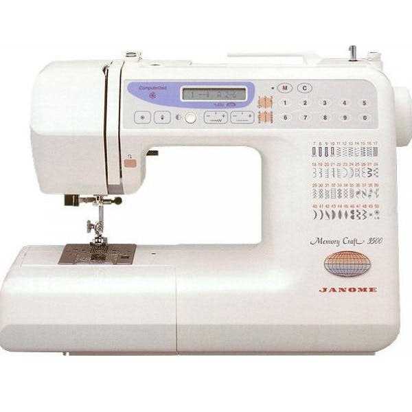
When working with textile tools, having a clear understanding of their components is essential for both efficiency and longevity. Knowing the internal structure helps ensure smooth operations and timely repairs. Each tool comes with a variety of elements that play distinct roles, all of which work together to create a seamless user experience.
Familiarizing yourself with these essential elements allows you to quickly identify and address any issues that might arise. Whether for routine maintenance or troubleshooting a malfunction, recognizing the individual components helps avoid unnecessary repairs. The better you understand how everything fits together, the easier it becomes to ensure your equipment performs at its best.
This guide will provide insights into the key features of your device, helping you navigate through its structure and make well-informed decisions regarding its upkeep. Understanding each section of the tool can significantly improve its efficiency and extend its working life.
Understanding the Essential Components
Each textile tool is made up of several crucial elements that work in unison to ensure efficient operation. A clear understanding of these components allows users to maintain their equipment and identify potential issues. Knowing how each element interacts with the others makes it easier to troubleshoot and perform necessary repairs. These key features are fundamental to achieving the best performance from your device.
Main Functional Elements
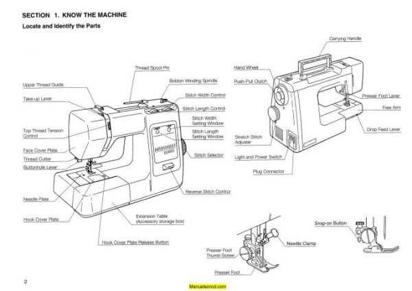
The core components of any textile device include mechanisms that control movement, feed, and threading. These parts are responsible for the smooth operation of the tool, allowing users to achieve precise results. Understanding their roles can help you quickly detect issues such as misalignment or wear that could affect performance. Regular inspection of these components is crucial for avoiding disruptions during use.
Supporting Elements for Enhanced Performance
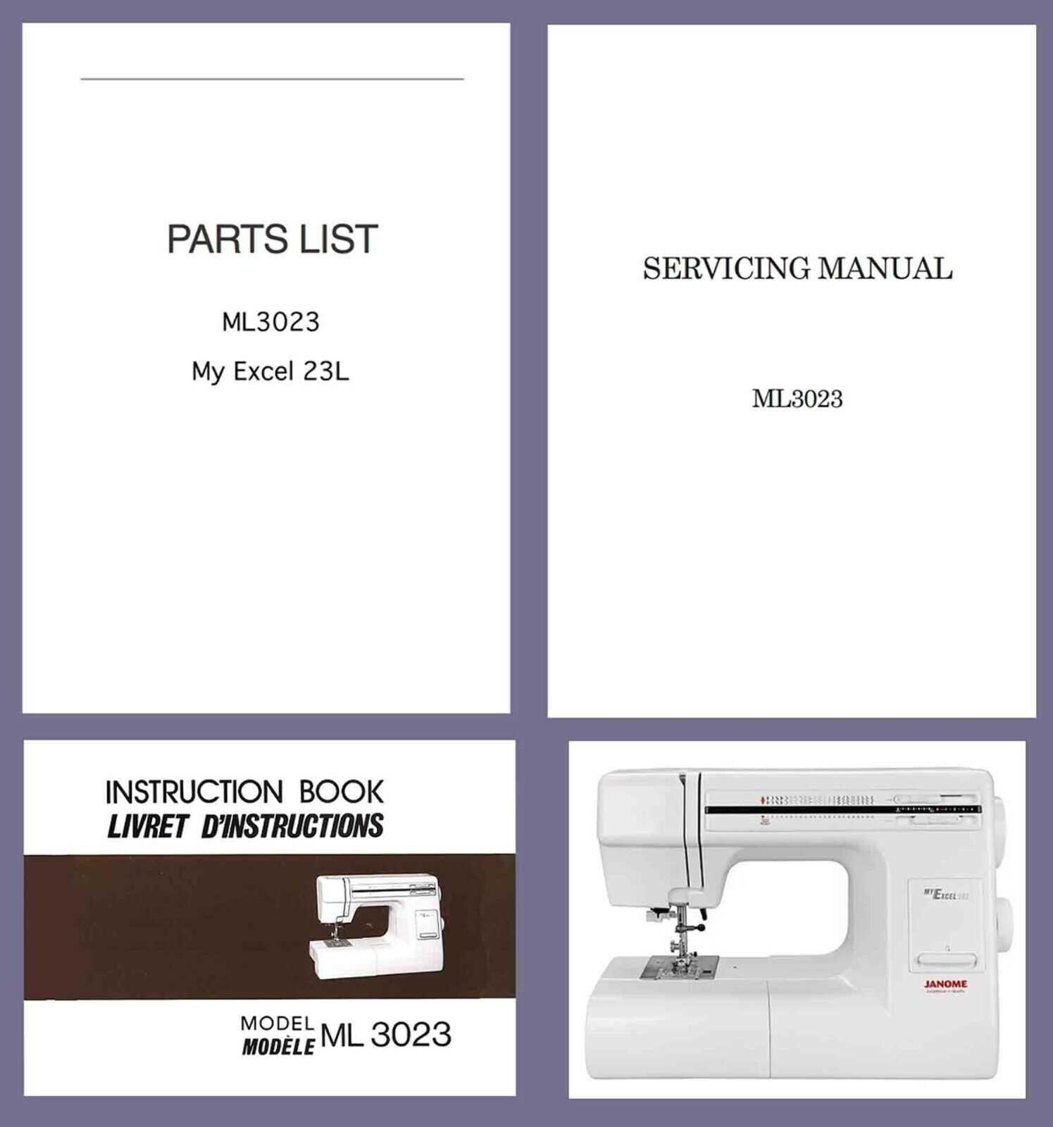
In addition to the primary functional mechanisms, there are smaller supporting elements that help enhance the overall efficiency of the tool. These may include features that improve stability, reduce vibrations, or ensure optimal tension. While they may seem less significant, they play an important role in maintaining consistent quality over time. Familiarizing yourself with these supporting elements ensures a well-rounded understanding of the entire setup.
Key Parts in Textile Devices Explained
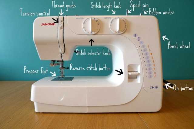
Understanding the primary components of any textile tool is crucial for its effective use and maintenance. Each element plays a specific role that contributes to the overall functionality of the device. When these parts work together harmoniously, the result is optimal performance, allowing users to complete their tasks with ease and precision. Knowing what each component does makes it easier to diagnose problems and perform routine upkeep.
Main Drive Mechanism
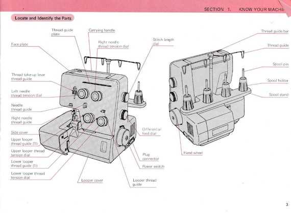
The central mechanism responsible for driving the tool’s operations is typically the motor and the associated drive system. This mechanism controls the movement of the working parts and ensures they move at the correct speed and force. Regular maintenance of this system is essential, as it directly impacts the overall performance of the device.
Threading System
The threading system is another crucial component that ensures the proper path and tension of the threads. This system allows the material to be stitched effectively. Any issue in the threading system can lead to tension problems or skipped stitches. A well-maintained system allows for smoother operation, providing consistent results.
How to Use the Components Layout for Repairs
When attempting repairs on your textile tool, having a visual guide of its internal structure is invaluable. A clear representation of all the key elements allows you to easily identify damaged or worn-out components. With the help of such a reference, troubleshooting becomes more efficient, and pinpointing the exact cause of any malfunction is much simpler.
Identifying Faulty Parts
By referring to the component layout, you can locate each section of the device and check for any signs of wear or malfunction. Knowing where each element is situated allows you to quickly determine which parts need attention. In many cases, this visual guide will help you narrow down the issue without needing to disassemble the entire tool.
Guided Replacement and Adjustment
Once you’ve identified the faulty component, the guide can also show you how to properly remove and replace it. Whether it’s adjusting tension, lubricating moving parts, or replacing broken elements, the layout ensures you’re following the correct procedure. This step-by-step approach minimizes the risk of causing further damage while improving the overall efficiency of your repairs.