Maintaining outdoor equipment in optimal condition is crucial for its longevity and performance. Knowing the layout of key components and how they fit together is essential for any repair or maintenance task. Whether you are a professional or a hobbyist, understanding the internal structure of your machinery can help you identify issues quickly and make informed decisions about replacements or repairs.
Proper knowledge of assembly and disassembly can save both time and money. By exploring the components and their interconnections, you gain the ability to troubleshoot and efficiently address any malfunction. Recognizing common wear parts and knowing where to find reliable replacements will ensure your equipment continues to function at its best.
In this guide, we will break down the parts layout of your equipment, helping you understand the critical components and how to care for them. This knowledge is invaluable for anyone looking to maintain their tools in top working order.
Understanding the Husqvarna 130bt Parts Layout

When working with outdoor equipment, having a clear understanding of its internal organization is crucial for effective maintenance and repair. The layout of the various components forms the foundation for troubleshooting and identifying issues that may arise. By familiarizing yourself with how the different pieces connect and function together, you can ensure that each part performs optimally, reducing the risk of malfunction and wear over time.
This section focuses on breaking down the equipment’s structure, offering a comprehensive overview of its core elements. Recognizing how each component supports the others allows you to navigate repairs with confidence, whether you’re replacing a single item or conducting a full inspection. Understanding the organization of the machine also empowers you to make quick assessments when problems occur.
Knowing the precise arrangement of essential components not only helps in diagnosing faults but also guides proper assembly during repairs. With this knowledge, you are better equipped to identify the right replacements, ensuring your tool is always in peak condition.
Identifying Common Replacement Parts for Husqvarna 130bt
Routine maintenance often involves replacing components that wear down with use. Knowing which parts are most likely to need attention can help you stay prepared and avoid costly repairs. The wear items in any machine are typically those that experience the most stress during operation, such as moving parts, seals, and filters. Identifying these components is the first step toward ensuring your equipment runs smoothly for years.
Common Wear Components
Some of the most frequently replaced items include air filters, fuel filters, spark plugs, and drive belts. These components are crucial for maintaining the performance and efficiency of the machine. Regular checks and timely replacements of these items prevent bigger issues that could arise from neglecting them.
Essential Hardware and Tools
Additionally, nuts, bolts, and springs are integral to keeping the machine together. They may loosen over time and need replacing. Using the right tools to secure and replace these small yet important parts is vital for long-term reliability. Identifying these common parts early helps keep your equipment functioning at its best with minimal downtime.
How to Use the Husqvarna 130bt Parts Diagram
Knowing how to interpret a visual representation of your machine’s components is essential for effective troubleshooting and repairs. A well-organized map of the internal structure provides clarity on where each piece fits and how they interact. This allows you to identify any faulty or worn-out parts with ease, making the process of maintaining your equipment much more efficient.
Locating and Identifying Components

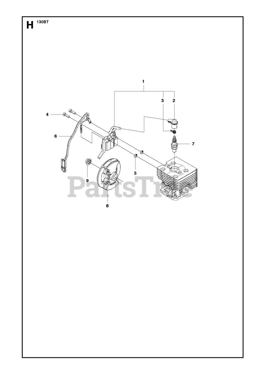
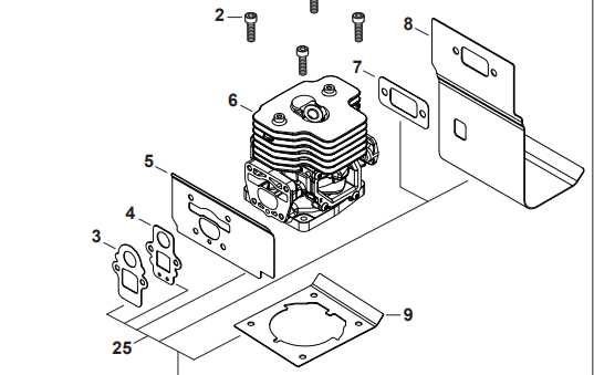
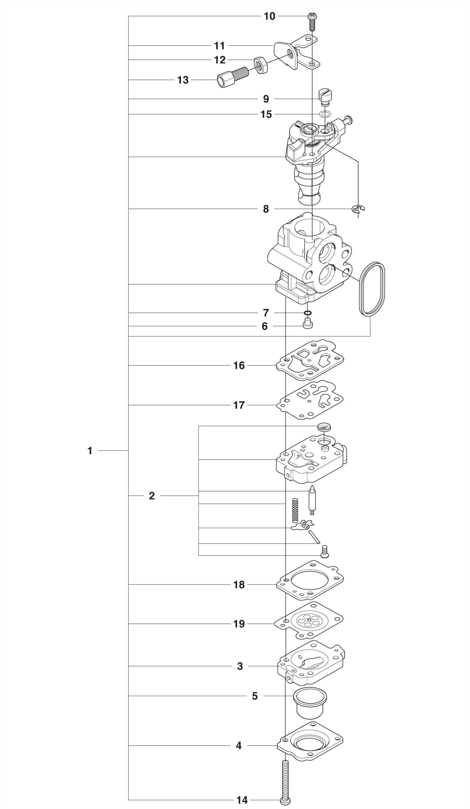
Start by locating the specific part you need to replace. The diagram will usually have labels or numbers to help you pinpoint the exact item. By understanding the layout, you can quickly find the part’s location and understand its function within the overall system. This is particularly helpful when dealing with complex machinery where multiple components work together.
Checking Compatibility and Replacements
Once you’ve identified the part, the next step is checking its compatibility with available replacements. The diagram can guide you through finding similar components or verifying part numbers. This step ensures you get the correct replacement that will fit and function as intended, minimizing the risk of mismatches or improper repairs.