Maintaining the proper function of agricultural machinery is essential for efficiency and longevity. Understanding the internal structure and individual elements of these machines can greatly assist in identifying issues and performing repairs. A clear visual reference of key components helps owners and mechanics navigate the complexity of modern tractors with ease.
In this section, we provide a comprehensive visual representation of a specific tractor model. The detailed map of its main components allows users to pinpoint parts, explore their interconnections, and understand their roles. With this knowledge, maintenance tasks become more manageable and troubleshooting less daunting.
By gaining insight into how each part fits into the larger system, users can ensure that their equipment continues to perform at its best. Whether you’re a first-time owner or a seasoned technician, this guide offers a valuable resource for efficient upkeep.

Kubota L3010 Tractor Component Breakdown

Understanding the structure and layout of agricultural machinery is crucial for effective maintenance and repair. Each element plays a vital role in ensuring the smooth operation of the machine, and knowing how they interact is essential for diagnosing problems and performing repairs efficiently. A detailed overview of these components gives users the clarity needed to identify and address any issues that may arise.
In this section, we will break down the main sections and features of the machine, offering a close look at the essential mechanical and electrical elements. From the engine to the transmission system, each part is interconnected, contributing to the overall functionality. Knowing where each component fits and its specific function makes troubleshooting simpler and more precise.
This guide provides a valuable resource for owners and technicians alike. Whether it’s for routine maintenance or addressing specific faults, having a clear understanding of the different systems within the machine will lead to better performance and extended service life.
Understanding the Parts Layout and Diagram

To ensure efficient operation and troubleshooting of machinery, it’s crucial to understand the layout and configuration of its main components. A well-structured visual representation allows users to quickly identify and locate key elements, making maintenance tasks more accessible and accurate. Such diagrams offer a roadmap of the system, illustrating how different sections work together to keep the machine running smoothly.
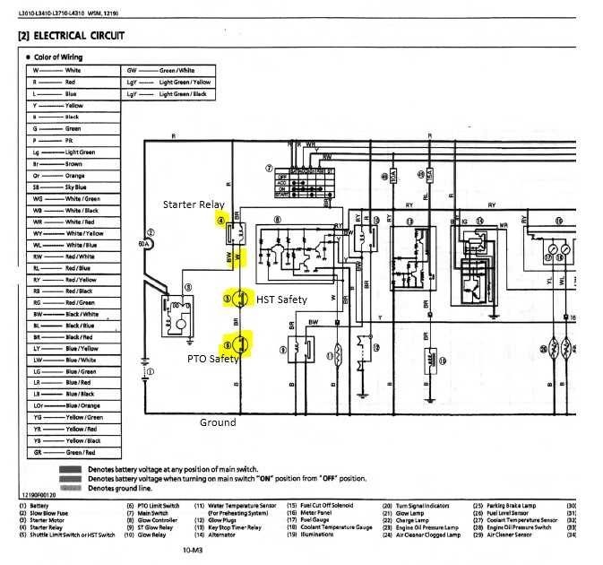
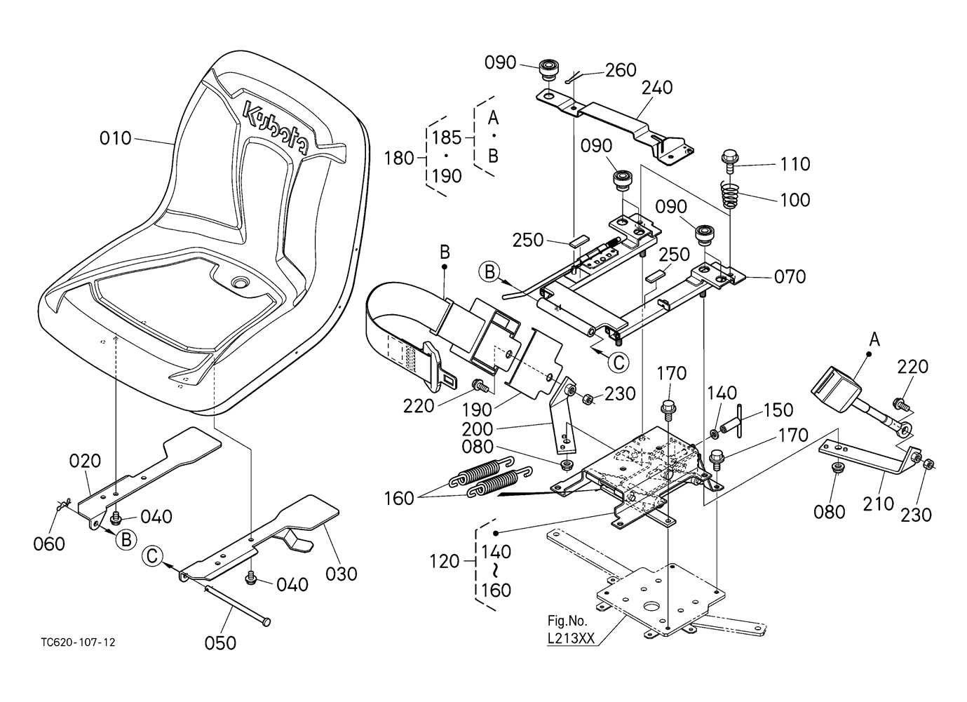
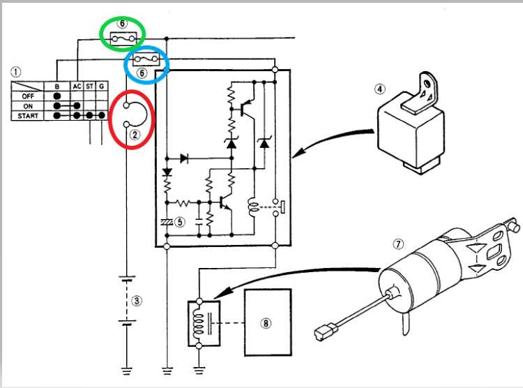
These visual guides are designed to highlight each major component and its position within the machine. By providing clear illustrations of the mechanical, electrical, and hydraulic systems, users can easily recognize parts that may need attention or replacement. A proper understanding of the layout enhances the ability to perform routine checks and diagnose any faults that may occur over time.
By mastering the layout of a machine, operators can not only improve efficiency but also ensure a longer lifespan for their equipment. This knowledge empowers users to make informed decisions during repairs and replacements, leading to less downtime and more effective management of their machinery.
How to Use the Kubota L3010 Diagram

Using a detailed visual guide of a machine’s components is an essential skill for both operators and technicians. By understanding how to navigate this visual representation, users can efficiently locate parts and determine their functions within the system. The key to making the most of such a resource is recognizing how each section of the diagram relates to the physical layout of the machinery.
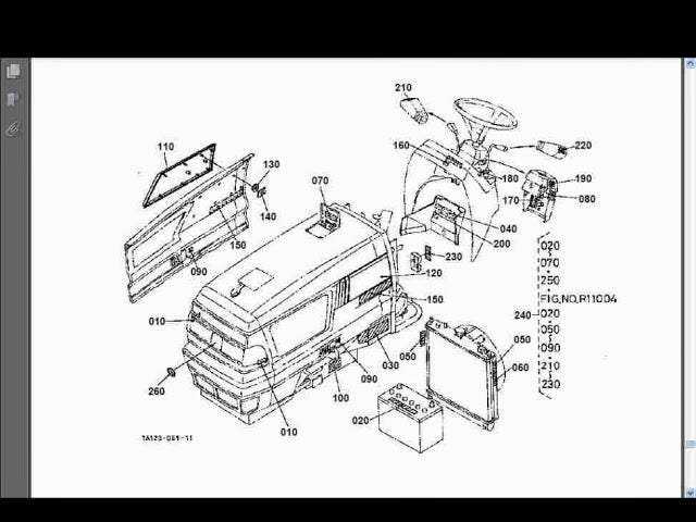
Start by familiarizing yourself with the overall layout, which divides the machine into various subsystems such as the engine, transmission, and electrical components. Each section will be clearly marked, allowing you to quickly identify the area you’re working with. Pay attention to part numbers and references, which will guide you in finding the exact components when searching for replacements or during troubleshooting.
Once you’re comfortable with the visual format, use the guide as a reference tool during repairs, inspections, or maintenance tasks. Whether you’re checking for wear and tear or replacing damaged parts, the diagram serves as a valuable aid in pinpointing the precise components that need attention, ultimately improving the efficiency and accuracy of your work.