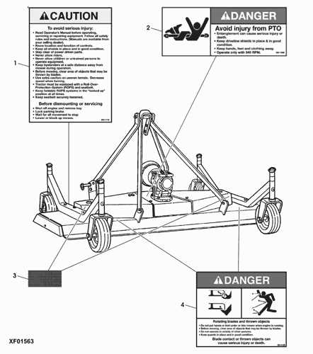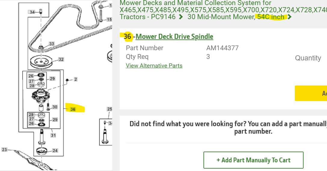
When maintaining heavy machinery, having a clear understanding of its individual components and their arrangement is crucial for effective repairs and upkeep. Knowing where each part fits and how they interact with one another ensures that you can troubleshoot issues efficiently and reduce downtime.
For those working with agricultural equipment, the ability to decipher visual layouts of key machinery is invaluable. These illustrations serve as detailed maps, highlighting all the essential pieces that make up the system. Familiarity with such resources can greatly simplify the process of identifying and replacing faulty elements.
Maintaining your equipment becomes far more manageable once you have a solid grasp of its structure. Whether you’re performing routine maintenance or tackling more complex repairs, having access to these guides allows you to perform tasks with confidence and precision. With the right knowledge, you can keep your machine running smoothly for years to come.
Understanding the Machinery Components
To ensure smooth operation of any heavy-duty equipment, it’s essential to have a clear understanding of its individual components. Knowing how each element functions and where it is located allows operators and maintenance teams to diagnose issues, perform repairs, and optimize overall performance.
The mechanical system of a tractor is made up of various interconnected pieces, each playing a specific role. These elements work together to power the machine and execute its tasks efficiently. Identifying and understanding the placement and purpose of each component is key to managing its upkeep and avoiding costly repairs.
Regular inspection of the equipment’s layout is crucial for detecting wear and tear, as well as potential breakdowns. With a thorough knowledge of how the system is structured, operators can maintain proper function and avoid issues that could hinder the machine’s productivity. Proper training and reference to the component layout are vital for successful equipment management.
How to Read a Parts Diagram

Understanding how to interpret a visual representation of machinery components is essential for proper maintenance and repair. These illustrations are designed to show the layout of each individual piece, helping operators identify the correct part and its specific location. By mastering this skill, you ensure that you can address issues more efficiently and with greater precision.
Breaking Down the Layout
The first step in reading a schematic is to familiarize yourself with the layout and structure of the diagram. Each symbol or image represents a unique component, and lines or arrows indicate how they connect or interact with other parts. Pay close attention to the labels and numbering that guide you to the specific part you need.
Understanding Labels and Numbers
Accurate identification of parts relies heavily on understanding the annotations that accompany the image. These typically include part numbers, descriptions, and sometimes measurements or specifications. Refer to a catalog or manual to cross-check these labels with the actual equipment, ensuring you have the right components for your repair or replacement needs.
Common Issues and Solutions for GM1072E
Heavy equipment is built to withstand tough conditions, but even the most durable machines can encounter issues over time. Regular maintenance and understanding common problems can help prevent downtime and improve the longevity of the machine. Knowing what to look for and how to address issues promptly can save time and resources.
Below are some of the most common problems and their corresponding solutions:
- Engine overheating: This issue may arise due to a clogged radiator or low coolant levels. Ensure the radiator is clean, and check coolant levels regularly. If necessary, replace old coolant.
- Worn-out belts: Over time, belts can wear out or become loose, affecting performance. Inspect belts regularly for cracks or excessive wear and replace them if needed.
- Hydraulic leaks: Leaks in the hydraulic system can lead to a loss of power and efficiency. Check hydraulic hoses for signs of wear, and tighten any loose connections to prevent leakage.
- Electrical failures: Electrical issues can be caused by faulty wiring or worn-out connectors. Inspect the wiring system for damage and ensure connections are secure.
By addressing these problems early on and performing preventive measures, you can keep your machine in optimal working condition and avoid costly repairs.
Identifying Key Components in the Diagram
Accurately identifying the main elements of any machinery is crucial for successful repairs and maintenance. The visual layout of a machine offers a clear guide to understanding the placement and function of each component. By becoming familiar with these key elements, you can more easily troubleshoot issues and ensure the machine operates at its best.
Each machine layout is designed to highlight essential components, such as the engine, transmission, hydraulics, and control systems. By recognizing these key pieces, operators and technicians can pinpoint potential problems and address them before they become major failures.
Familiarize yourself with the labels and symbols used in the visual representation. These are often accompanied by numbers or references that help you identify each component quickly. Cross-referencing these identifiers with the machine’s manual ensures accurate identification and smooth operation during repairs or routine checkups.
Step-by-Step Guide to Assembly
Assembling complex machinery requires careful attention to detail and a methodical approach. By following a clear step-by-step process, you can ensure that all components are correctly installed and properly connected, leading to efficient operation. This guide outlines the essential steps for putting together various sections of the equipment, ensuring that nothing is overlooked.
Start by reviewing the entire set of components and organizing them in a way that makes them easy to access. Group similar items together and ensure that all necessary tools are on hand before beginning the assembly. This preparation reduces confusion and enhances the efficiency of the process.
Next, follow the logical sequence of assembly, starting with the foundational elements such as the frame or base. Gradually build upon this structure by adding each component in the correct order, ensuring proper alignment and secure attachment at every step. Double-check each connection to avoid errors and ensure safety.
Finally, after completing the assembly, conduct a thorough inspection to verify that all parts are correctly installed and functioning as intended. Perform any necessary tests to confirm that the machine operates smoothly, and be sure to address any issues before use. Regularly reviewing the assembly process will help streamline future builds and maintenance tasks.