In this section, we delve into the intricate structure of early mechanical systems, focusing on the key components that allow them to function effectively. By examining the relationships between various elements, we can gain a clearer understanding of how these devices convert energy into motion.
The interdependence of each part ensures that the entire system operates smoothly. By studying the layout and function of these elements, one can appreciate the engineering behind these innovative machines, which played a significant role in the industrial revolution.
Efficient operation relies on a well-thought-out arrangement of critical components. Each part has a distinct role, contributing to the overall performance of the machine. Understanding these roles is essential for anyone interested in the historical development of mechanical technology.
Overview of Steam Engine Parts

Understanding the core elements of a mechanical system reveals how its various components work together to achieve movement and power. Each component plays a critical role, contributing to the machine’s overall function and efficiency. When these individual pieces are arranged and interact correctly, they enable the device to convert heat energy into useful mechanical motion.
At the heart of this system is the core assembly responsible for creating the necessary force to drive the mechanism. Other supporting elements, such as valves, pistons, and levers, are crucial in controlling the flow of energy and ensuring smooth operation. These components are strategically placed to optimize performance and maintain consistent functionality over time.
Each individual piece is designed to withstand the demands of high pressure and intense movement. Understanding the function of these elements and their connections helps explain how the entire system operates in harmony, transforming thermal energy into kinetic energy that powers machinery.
Understanding the Key Components

To fully grasp how a mechanical system functions, it is important to understand the primary elements that contribute to its operation. These components work in unison to convert energy into motion, each having a specific role that ensures the overall efficiency of the device. By analyzing these key pieces, we can gain insight into the system’s complexity and performance.
The Power Source
At the center of the mechanism lies the power source, which generates the necessary force to set everything in motion. This component is responsible for producing the energy that drives the rest of the system. Without this element, the machine would be unable to operate, making it essential for the overall function.
Motion Control Elements
In addition to the power source, there are several elements responsible for controlling and directing the flow of motion. These components ensure that the generated energy is properly harnessed and transferred to other parts of the system. They regulate speed, direction, and force, allowing for smooth and controlled operation throughout the entire machine.
How Steam Engines Operate
The functioning of a mechanical system designed to convert thermal energy into motion relies on a precise sequence of events. When heat is applied, it causes the fluid inside the system to expand, creating pressure. This pressure is then used to move specific components, which in turn generate movement and power. Understanding how this process unfolds helps explain the operational mechanics of such devices.
The process begins with the creation of pressure through the application of heat. As the fluid inside the chamber expands, it pushes against a piston or another form of moving part. This motion is then transferred to various mechanical elements, ultimately resulting in the desired movement. Each component plays a specific role in maintaining the balance and efficiency of the system.
| Step | Description |
|---|---|
| 1. Heating | The fluid is heated, causing it to expand and generate pressure. |
| 2. Pressure Build-up | The pressure pushes against the moving components, initiating motion. |
| 3. Transfer of Motion | The movement is transferred through various parts to generate mechanical work. |
Exploring the Mechanical Functionality

Understanding the way various components of a machine interact to produce movement reveals the intricate design behind their functionality. These devices rely on a series of mechanical processes that convert thermal energy into usable motion. By closely examining the flow of force through each element, we can better appreciate how each piece contributes to the overall performance of the system.
Energy Conversion
The core process begins with converting heat into pressure, which is then used to power the system. This pressure causes a component to move, which then transfers energy to other interconnected elements. Efficiency is key in this process, as the smoother the flow of energy, the more effective the device becomes in generating motion.
Force Transmission
Once the pressure initiates movement, the force is transmitted through a series of mechanical linkages. These components ensure that the generated motion is directed to the correct locations, ultimately performing the work required. The precision with which this transmission occurs determines the system’s reliability and stability, allowing it to operate under various conditions without failure.
Visual Guide to Steam Engine Diagrams
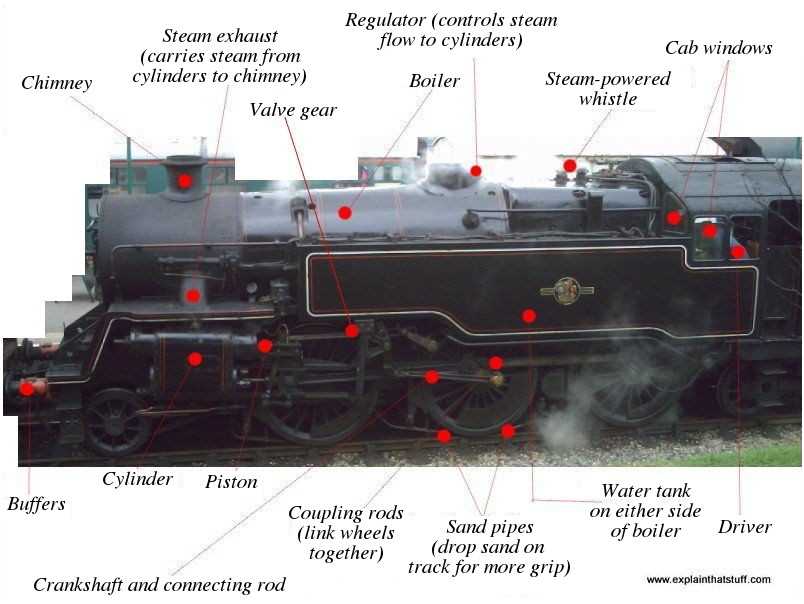
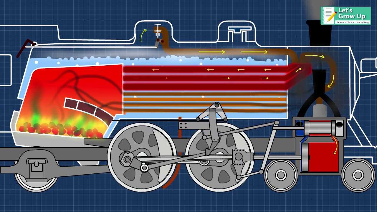
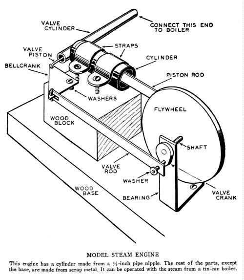
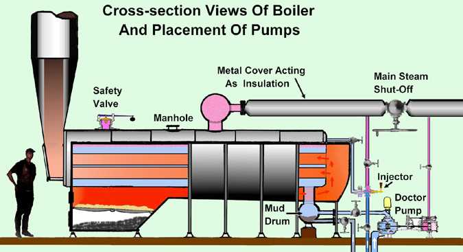
A clear understanding of how mechanical systems operate is often best achieved through visual representation. Diagrams and schematics allow for a detailed look at the various components and their interconnections, providing a clearer picture of how the system functions as a whole. By studying these visual aids, one can see the arrangement and relationship between the critical elements involved in energy conversion and motion generation.
These illustrations typically highlight the flow of energy, the movement of components, and the direction in which force is applied. A well-constructed visual guide can break down complex processes into understandable steps, making it easier to identify each element’s role and how they work together.
- Clarity: Diagrams simplify complex systems, making them easier to analyze and understand.
- Efficiency: Visual representations highlight the most efficient layout of components.
- Function: By examining visuals, you can better grasp the function of each piece within the system.
Understanding these visuals helps not only in grasping the mechanics but also in troubleshooting and optimizing the system’s design. Whether you’re a beginner or an experienced technician, these guides provide invaluable insight into the inner workings of mechanical devices.