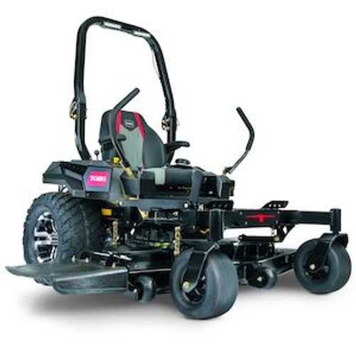
Proper maintenance and repair of lawn machinery can greatly extend its lifespan and ensure optimal performance. Understanding the different elements that make up these machines is crucial for anyone looking to perform DIY repairs or simply gain a better understanding of how their equipment functions.
Each machine consists of various essential components, each playing a specific role in its operation. By studying a well-organized visual representation, users can quickly locate individual parts and understand how they work together. This knowledge can save time and effort when diagnosing issues or replacing worn-out elements.
In this guide, we’ll explore the main features that are commonly represented in detailed equipment schematics. These diagrams offer a clear overview of the layout and connections, making it easier for users to identify components that need attention. Whether you’re an experienced technician or a novice, having access to this type of information can enhance your ability to troubleshoot and maintain your equipment effectively.
Understanding Lawn Equipment Components
When it comes to maintaining and servicing large outdoor machinery, having a clear understanding of its internal structure is essential. Each device is made up of several key elements, which interact with one another to perform specific tasks. Knowing how each part functions allows users to carry out maintenance with greater efficiency and precision, ensuring the equipment runs smoothly.
At the core of every machine is a set of components that work together in harmony. These include various mechanical, electrical, and structural elements, each with its own role. By becoming familiar with the main sections of the machine, users can pinpoint areas that may need repairs or replacements. Understanding these connections and how they affect the overall operation is crucial for effective troubleshooting.
Additionally, certain elements are more prone to wear and tear, such as belts, pulleys, and filters. Knowing where these parts are located and how to replace them can help you maintain your equipment without the need for professional intervention. Comprehensive knowledge of these components, combined with proper care, can prevent many common issues and help keep your machine in top condition for years to come.
Key Components in the Visual Representation
Understanding the core elements of your outdoor machinery is essential for successful maintenance and repair. The schematic provides an organized layout, highlighting crucial sections of the device that are vital for its operation. By breaking down the machine into individual components, users can easily locate and identify specific parts that need attention.
Among the most important components are the power source, the drive system, and the cutting mechanism. These are the foundational elements that allow the machine to function efficiently. The power source typically consists of an engine or motor that drives the entire system, while the drive system includes belts and gears that transmit power to the wheels or other moving parts. The cutting mechanism is responsible for executing the primary task, whether it’s mowing, trimming, or another action.
Additionally, understanding auxiliary elements like the control panel, safety features, and structural components is key. These parts ensure proper operation, safety, and durability. Familiarity with each section helps users quickly diagnose issues and perform necessary repairs without the need for outside assistance.
How to Use the Visual Representation for Repairs

When performing maintenance or repairs on outdoor equipment, a well-organized schematic can be an invaluable tool. It allows users to locate and identify specific sections quickly, ensuring that the right components are addressed. By using this guide, you can save time, avoid mistakes, and complete repairs with greater confidence.
Start by familiarizing yourself with the layout of the machine and its various sections. Each part is typically marked clearly, and you can follow the flow of energy or movement throughout the system. If you’re dealing with an issue, pinpoint the relevant area in the schematic to understand which components could be involved. For example, if there’s an issue with power delivery, you’ll likely focus on the engine, fuel lines, and related electrical components.
Once the problematic area is identified, follow the schematic to locate the specific component that may need repair or replacement. This guide will often show connections, bolts, and fasteners, allowing you to understand how to disassemble the parts safely. After replacing or fixing the faulty component, you can use the diagram to reassemble everything in the correct order, ensuring that all parts are properly aligned and securely fastened.