When working on model train maintenance or upgrades, having a clear understanding of the individual components and their assembly is crucial. This section will guide you through the different elements involved in a model’s structure and how they can be properly identified and assembled.
Clear visuals and detailed layouts can simplify the process of finding the right parts and making necessary adjustments. Whether you’re restoring a classic model or customizing a new one, knowing how to interpret these visuals is essential for efficient repairs.
Familiarity with the various sections will help you manage both simple fixes and more complex modifications, ensuring that each piece functions seamlessly in the system. Understanding how everything connects is key to mastering model train operations and achieving the best results.
Understanding Model Train Schematics
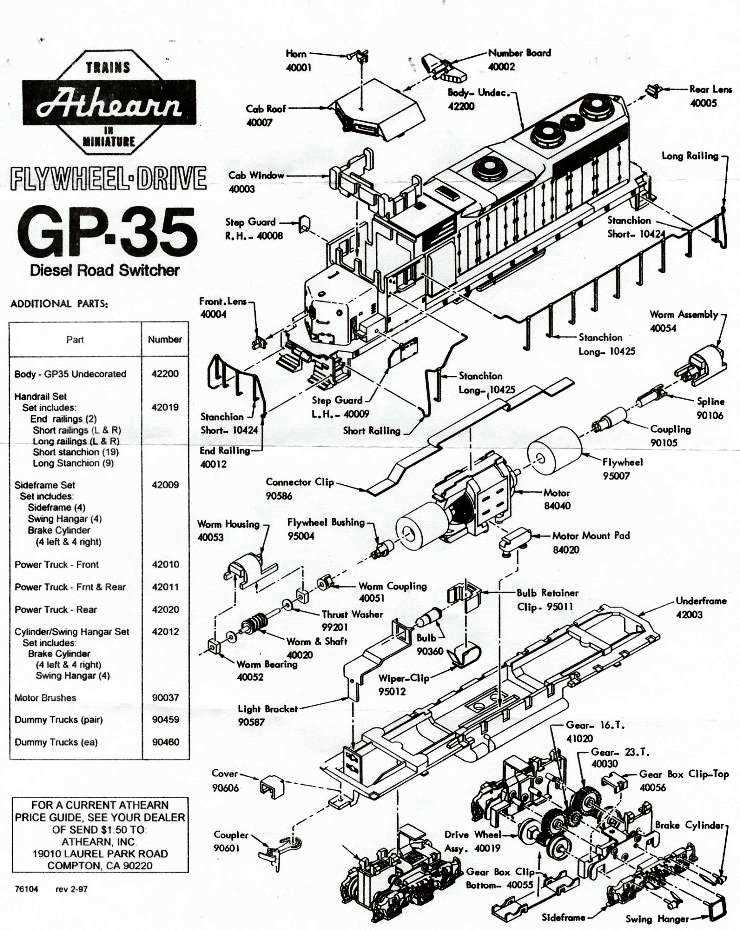
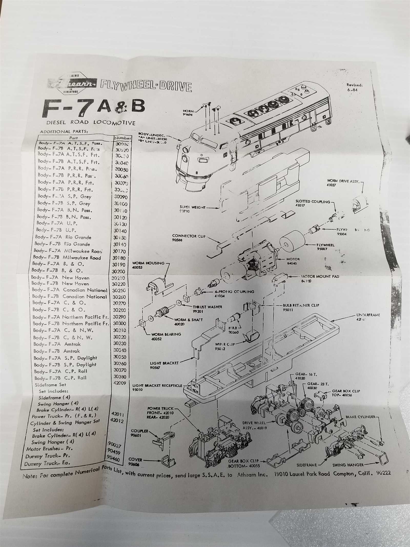
To effectively repair or customize your model train, it’s essential to comprehend the technical layouts that showcase how each component fits together. These visuals act as a roadmap, helping you identify individual elements and their respective functions within the system. A thorough understanding of these schematics will streamline your workflow and reduce the chances of errors during assembly or maintenance.
How to Interpret the Visuals
The key to using these layouts effectively is understanding the different symbols and markings used to represent the various elements. Most schematics will highlight parts such as motors, wheels, and wiring with clear indicators, enabling you to locate and work with each piece easily. Paying attention to the connections between elements ensures you can follow the structure accurately, whether you’re disassembling a part or reassembling it after maintenance.
Commonly Found Symbols and Their Meaning
Within the layout, specific symbols are used to denote different components or actions, such as movement or power flow. Recognizing these signs can save time and prevent confusion. For example, a dotted line might indicate a flexible connection, while a solid line could represent a fixed connection. Understanding these basic symbols provides a strong foundation for navigating complex models with confidence.
How to Read Model Train Schematics

Interpreting technical layouts for model trains requires a keen eye for detail and an understanding of the conventions used. These schematics are designed to break down complex assemblies into easily understandable parts, enabling you to follow a logical process for repairs or upgrades. Learning to read these visuals effectively will enhance your ability to work with model trains, whether you’re troubleshooting or enhancing performance.
Recognizing Key Components
The first step in understanding any layout is identifying the primary components. These could include motors, gears, wheels, or electronic connections. Each part is usually represented by a distinct symbol or shape, which corresponds to its real-world counterpart. By familiarizing yourself with these symbols, you can quickly pinpoint the elements you need to focus on, saving time during the repair or modification process.
Understanding Connections and Flow

In addition to individual parts, schematics often show how components are connected to one another. Lines and arrows are used to represent electrical connections or mechanical linkages. A solid line typically indicates a fixed connection, while dashed lines may show flexible or movable parts. Arrows indicate the direction of movement or electrical flow. Understanding these connections is crucial for ensuring proper assembly and avoiding mistakes during maintenance.
Common Model Train Components

Model trains consist of a variety of components that work together to create a functional and realistic system. Understanding these elements is essential for both maintaining your models and improving their performance. Each component plays a specific role, from ensuring proper movement to enabling electrical connectivity and power flow. Recognizing and knowing how to handle these parts will make repairs and modifications much more manageable.
Motors and Power Units
The motor is at the heart of the system, providing the power necessary to move the train. Depending on the model, you may encounter different types of motors, including DC or even more advanced digital units. These motors are usually connected to other elements like gears or wheels, transferring energy and enabling motion. Proper understanding of motor functions is vital for troubleshooting power-related issues.
Wheels and Gears
Wheels and gears are fundamental to the train’s movement and operation. Wheels are typically designed to provide smooth movement along tracks, while gears work to regulate speed and ensure accurate motion control. Over time, wear and tear can affect these components, leading to issues like slipping or uneven movement. Regular inspection and maintenance of wheels and gears are essential for optimal performance.