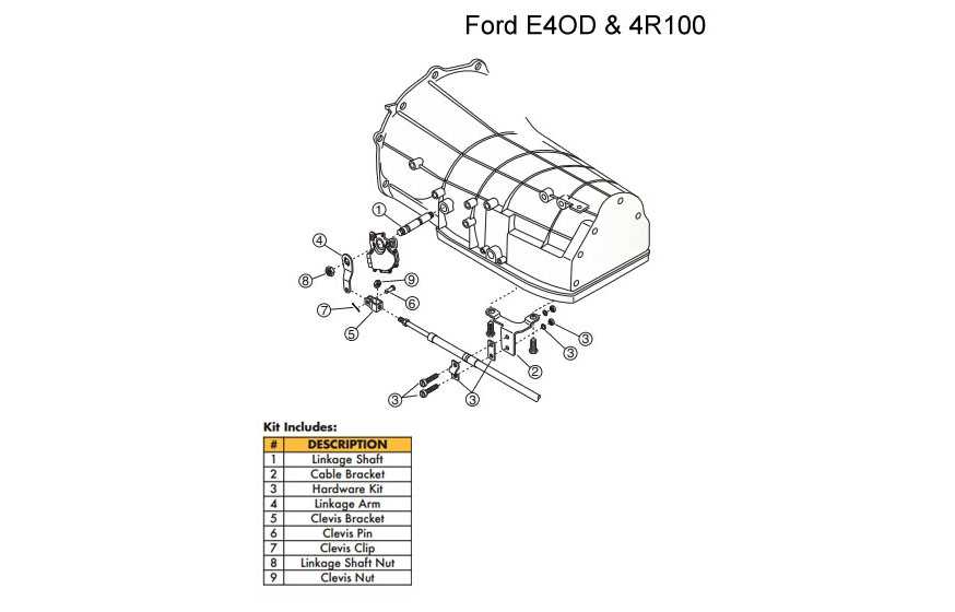
Understanding the layout of complex mechanical systems is crucial for both maintenance and repair tasks. A detailed visual representation can provide invaluable insights into the arrangement and function of various elements. Knowing the key parts and their interactions helps ensure smooth operation and efficient troubleshooting.
In this guide, we will explore a comprehensive overview of an automatic transmission, focusing on its major components and their roles. With a clear understanding of each element, you can confidently approach any maintenance, repairs, or upgrades needed to keep the system performing optimally.
Familiarizing yourself with how the different parts fit together and function can significantly simplify the diagnostic process. By using a clear schematic, technicians can easily pinpoint issues and take the appropriate steps for resolution.
Understanding the 4r100 Parts Layout
Gaining a clear understanding of the internal structure of a transmission system is essential for anyone working with or maintaining automatic gearboxes. A detailed map of the individual elements allows technicians to better understand their roles and how they interact with each other, which is crucial for effective troubleshooting and repair.
Key Components and Their Functions
The transmission consists of numerous components, each with a specific purpose. These include gears, shafts, and valves that work together to ensure smooth shifting and reliable performance. Knowing the exact placement of each piece and its function helps identify potential failure points and improve the efficiency of repair or maintenance procedures.
How to Read the Layout Effectively
To fully benefit from a schematic layout, one must be familiar with the general system of the transmission and how its parts function together. The layout typically illustrates the arrangement of the main components in relation to each other, showing how they are connected and interact during operation. Understanding this relationship is key for precise diagnostics and ensuring proper maintenance procedures are followed.
Key Components of the 4r100 Transmission
Automatic transmissions consist of a range of essential components that work in harmony to ensure seamless shifting and effective power delivery. Each part serves a specific function, and their careful coordination is what allows the entire system to operate smoothly under various conditions. Understanding the main elements is crucial for diagnosing issues and performing maintenance tasks.
Among the critical components are the gearsets, which control the various drive ratios, and the hydraulic system, which manages fluid pressure to engage and disengage the gears. Other essential elements include the valve body, which directs fluid flow, and the torque converter, which helps transmit engine power to the transmission. Recognizing the role of each part helps technicians address malfunctions with greater accuracy and efficiency.
How to Use the 4r100 Diagram Effectively

To make the most of a detailed schematic, it’s important to understand how to interpret the relationships between the various components. A well-structured layout serves as a guide to help identify specific parts, their functions, and their positions within the system. Properly using this visual tool can save time during diagnostics and maintenance by providing clear insights into the assembly.
Step-by-Step Approach to Reading the Layout

When studying the layout, follow these steps to make sure you understand the flow and connections:
- Start by familiarizing yourself with the overall structure, noting how the components are organized.
- Identify the main sections, such as the transmission housing, valve body, and hydraulic system.
- Look for lines or markers that indicate the flow of fluids or power transmission between parts.
- Pay attention to the color coding or labels that may indicate specific functions or pressures.
Using the Layout for Troubleshooting
The schematic is a valuable tool when diagnosing issues within the system. By using it to pinpoint the exact location of malfunctioning components, you can quickly narrow down potential causes of failure. Here’s how to approach troubleshooting:
- Focus on the sections of the diagram where problems are suspected.
- Compare the visual information with known symptoms to identify discrepancies.
- Use the diagram to check connections, ensuring everything is properly aligned and intact.