Understanding the layout and structure of machinery components is essential for effective maintenance and repairs. When working with agricultural equipment, having a clear reference to each part helps in identifying issues, reducing downtime, and ensuring optimal performance. A well-detailed visual guide is an invaluable tool for any mechanic or farmer aiming to keep their equipment in top shape.
Effective maintenance relies on being able to locate and assess each individual element of the machine. This guide offers a clear representation of the different sections, ensuring you can quickly pinpoint the necessary parts for servicing. With this reference, both experienced and novice operators can approach repairs with confidence.
Knowing how components interact and where they are located enables more precise troubleshooting and minimizes the risk of unnecessary part replacements. Whether you’re replacing worn-out pieces or performing routine checks, having an accurate map of your machine is crucial for long-term success in the field.
Understanding the John Deere 2040 Parts Layout
To efficiently maintain or repair any complex machinery, it’s important to have a clear overview of its structure and components. Knowing the general layout allows you to quickly identify where each piece fits into the overall system, aiding in faster diagnostics and maintenance. Understanding this framework helps in recognizing potential areas that need attention and allows for more effective problem-solving.
Each section of the machine is designed to serve a specific function, and its arrangement is crucial for smooth operation. A well-organized visual guide ensures that you can follow the right sequence when working on repairs or replacements, minimizing errors. Whether dealing with mechanical or electrical elements, understanding the distribution of components within the machine can save time and effort in the long run.
Additionally, having a clear mental map of the machine’s internal structure helps in anticipating wear and tear on specific components. With this knowledge, you can prioritize maintenance tasks, extend the life of key elements, and ensure optimal performance throughout the equipment’s use. Knowing the layout is the first step toward becoming proficient at handling the machine’s upkeep.
How to Read the John Deere 2040 Diagram

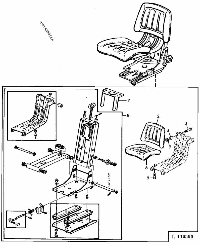
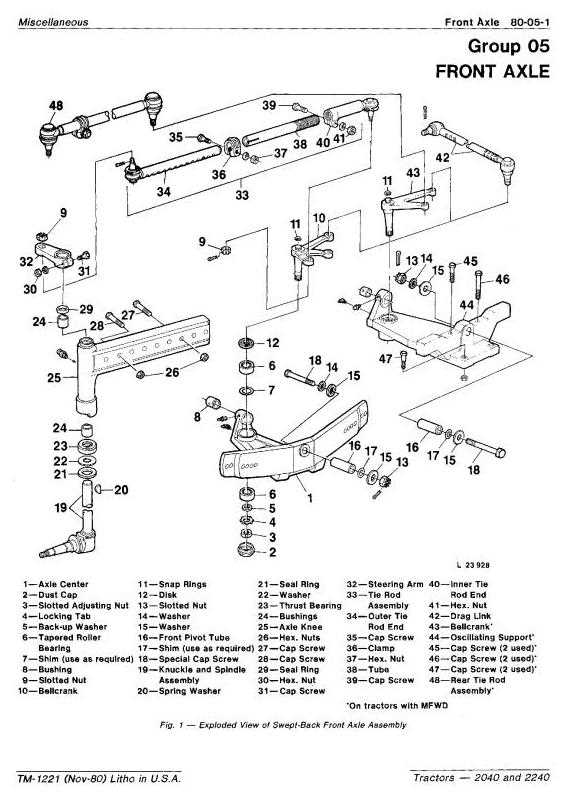
Interpreting a schematic representation of machine components is essential for anyone involved in maintenance or repairs. The layout provides a visual guide to the key elements, helping users understand how the various sections work together. Understanding how to read these references ensures that technicians can identify, locate, and address specific parts with precision.
Key Symbols and Notations
Each schematic uses standard symbols and notations to represent different components, such as mechanical parts, electrical systems, and hydraulic elements. Familiarizing yourself with these symbols is the first step in understanding the layout. Recognizing these key representations helps in navigating the diagram more effectively and reduces the risk of mistakes during repairs.
Step-by-Step Guide
Start by identifying the major sections of the diagram, such as the engine, transmission, and hydraulic systems. From there, focus on smaller components within each section. The diagram will often include part numbers and references to help you match the visual elements with physical components, enabling you to find the exact part needed for replacement or repair.
Common Repairs Using the Parts Diagram

When performing repairs on complex machinery, having a clear guide to identify each component is crucial. A schematic reference can significantly reduce downtime by helping technicians pinpoint issues faster and more accurately. Common repairs often involve replacing worn-out parts, addressing mechanical failures, or fixing electrical malfunctions. With a detailed visual guide, these tasks become more straightforward, ensuring that the right part is replaced and the repair is completed efficiently.
Engine issues are among the most frequent concerns. Using a visual guide, you can easily locate and identify malfunctioning parts like the fuel pump, air filter, or ignition system components. This allows for faster diagnostics and a smoother repair process.
Hydraulic system repairs are another common area where a schematic layout proves invaluable. It helps technicians identify faulty hoses, pumps, and valves, ensuring the entire hydraulic network is functioning properly. Regular maintenance of these systems is essential for maintaining optimal performance and preventing more serious failures down the line.
Electrical components, such as wiring and sensors, often require replacement or inspection. A clear representation of the electrical system allows you to trace connections and identify faulty wiring or damaged sensors quickly, reducing troubleshooting time.