Efficient operation and longevity of farming equipment depend on understanding its internal mechanisms and components. Recognizing the crucial elements of a machine helps in troubleshooting and ensuring smooth functionality. A clear understanding of how parts interact is essential for any user or technician.
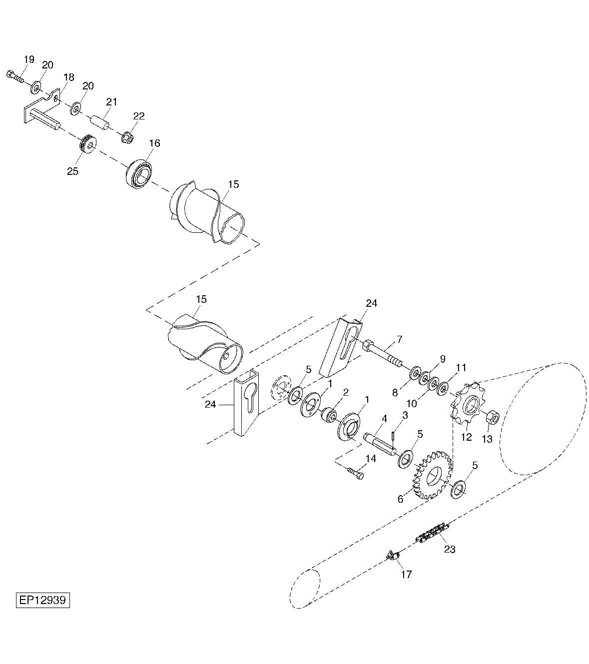
By referring to detailed visual guides, operators can easily identify the different sections and their roles in the overall machinery system. These diagrams serve as a vital tool in simplifying complex assembly structures, allowing users to pinpoint issues and perform repairs effectively.
Proper maintenance and timely repairs are key to preventing costly breakdowns. Knowing the individual functions of each piece is vital to maintaining peak performance and extending the lifespan of the equipment. Clear, visual representations make it easier for anyone involved in agricultural machinery upkeep to stay on top of essential tasks.
Understanding the Agricultural Pressing Machine
Efficiently managing hay and straw is critical for any farming operation. The pressing machine is an essential piece of equipment designed to compress loose materials into compact shapes for easy handling, storage, and transportation. Knowing the functionality and structure of this machine helps optimize its usage and maintenance.
This machine incorporates several key mechanisms that work together to achieve optimal performance. Familiarity with these components ensures the operator can handle repairs, replacements, and maintenance tasks more efficiently. Understanding the assembly layout also simplifies troubleshooting, reducing downtime.
- Feed system: Directs material into the press for proper compression.
- Compression chamber: Compresses the material into a compact form.
- Tie-off mechanism: Secures the final shape for easy removal.
Having an in-depth understanding of each section’s role within the system can significantly improve overall operational efficiency. Regular inspection and upkeep of each part help prevent malfunctions and extend the machine’s useful life, ultimately increasing productivity in the field.
Key Components of the Agricultural Pressing Machine

To achieve efficient and reliable operation, a pressing machine is composed of several crucial components that work together seamlessly. Understanding these elements helps ensure the equipment functions optimally, allowing for smooth operation and minimal downtime. Each part has a distinct role in the overall process, and proper maintenance of these components is key to the machine’s longevity.
Feeding and Compression System

The feeding system plays an essential role in guiding the material into the machine for processing. This mechanism ensures that the incoming material is properly aligned and directed into the compression chamber. Once inside, the material undergoes compression, which is the core function of the system. The compression chamber is designed to apply the necessary force, reducing the size and increasing the density of the material.
Tie-off and Ejection Mechanisms
Once the material is compacted into the desired shape, the tie-off mechanism secures it, ensuring that it remains in place until it is ejected. This component is critical for maintaining the consistency of the final product. After securing the material, the ejection mechanism removes the finished shape from the machine for storage or transport. Proper functioning of these components guarantees smooth operation and minimizes delays.
Regular checks of these key components are essential to maintaining efficiency and preventing malfunctions. By ensuring that each part performs its intended function, operators can reduce the risk of breakdowns and enhance the machine’s productivity.
How to Read the Component Layout
Understanding how to interpret the layout of machine components is crucial for efficient maintenance and repairs. These visual guides are designed to provide a clear representation of the machine’s internal structure, highlighting each individual piece and its role in the system. By reading and analyzing these illustrations, operators can identify the exact location of components and how they interact with each other.
Identifying Key Elements
The first step in interpreting a layout is recognizing the different sections of the machine. Each part is typically labeled, often with a reference number that corresponds to a detailed list. These numbers make it easier to locate specific components and understand their functions. Pay attention to the orientation and placement of each piece within the larger system to get a sense of how the entire mechanism operates.
Understanding Part Relationships
Once individual components are identified, it is important to understand their relationships to one another. The layout often shows how parts are connected, such as through mechanical linkages or fasteners. Recognizing these connections is vital for troubleshooting issues and ensuring that all components are functioning as intended. It can also guide you in dismantling or reassembling parts with accuracy.
By regularly consulting these layouts, operators and technicians can gain a deeper understanding of the machine’s design and improve their efficiency in handling repairs and maintenance tasks.