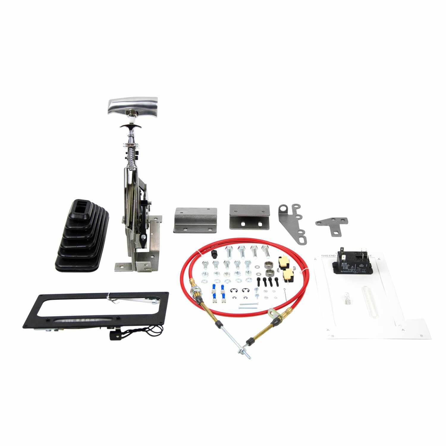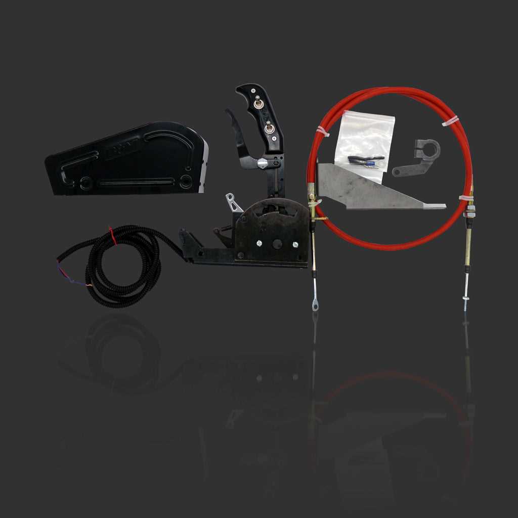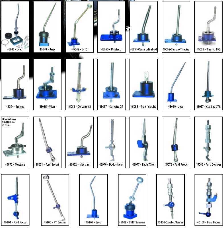
When it comes to high-performance vehicles, precise mechanical control is essential for achieving optimal handling and shifting. Understanding the inner workings of these systems allows enthusiasts and professionals alike to maintain and upgrade their gear mechanisms effectively.
Detailed schematics play a crucial role in visualizing how the various elements interact, enabling better understanding of their functions and placement. These illustrations provide a roadmap for assembly, troubleshooting, and enhancement.
By exploring the structure and arrangement of individual components, users can gain insights into potential areas for improvement and repair. Proper knowledge of these systems ensures longevity and smooth operation, making them indispensable for maintaining peak vehicle performance.
Understanding Performance Gear Components
In high-performance vehicles, achieving precise control over gear transitions is vital for smooth operation and quick response times. Each element of the system plays a specific role, contributing to the overall functionality and effectiveness of the mechanism.
The key to enhancing these systems lies in understanding how individual components interact with each other. By breaking down the essential pieces, one can better appreciate their functions and how they contribute to seamless gear shifts during operation.
Knowing the layout and purpose of each component ensures that users can troubleshoot, upgrade, or maintain their gear mechanisms with confidence, ensuring improved performance and durability for their vehicles.
How to Read Performance Gear Schematics

Understanding visual representations of mechanical systems is essential for anyone looking to maintain or upgrade vehicle components. These detailed illustrations provide a clear map of how various elements are positioned and interact within the system.
When examining these schematics, it is important to familiarize yourself with the symbols and labels used to represent each individual piece. This allows for a better understanding of their role and placement within the broader structure, ensuring the correct assembly and functionality of the entire system.
By carefully analyzing these technical drawings, users can identify potential issues, understand the correct positioning of each part, and ensure proper installation, all of which are key to maintaining high performance and reliability.
Common Issues with Gear Mechanism Components
When working with mechanical control systems in vehicles, certain issues can arise that affect performance and functionality. Identifying these problems early can help prevent costly repairs and ensure smooth operation over time.
Wear and Tear on Components
Over time, frequent use of the gear system can lead to wear on various components, such as connectors and springs. This can result in slower or inconsistent response during gear transitions. Regular maintenance and replacement of worn-out pieces are essential for optimal performance.
Incorrect Alignment of Parts

Improper alignment of components can lead to difficulty in shifting, creating resistance or even preventing smooth transitions. Ensuring that all elements are properly aligned according to the manufacturer’s specifications is crucial for effective operation and reliability.