When working with any power tool, knowing its inner workings is crucial for effective maintenance and repair. A clear understanding of its structure helps identify potential issues before they become major problems. By familiarizing yourself with the tool’s different sections, you can ensure smoother performance and extend its lifespan.
Accurate identification of each individual part is key to troubleshooting and replacements. Whether you’re looking to repair a malfunction or perform routine upkeep, being able to locate and understand the role of each component is essential. This process also minimizes the need for professional intervention, saving both time and money.
In this guide, we will explore how you can use detailed diagrams to better understand your tool’s layout. We will show you how to easily pinpoint specific pieces and walk you through the steps of ensuring your equipment stays in optimal working condition.
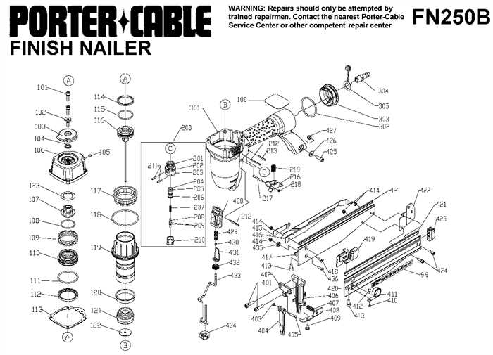
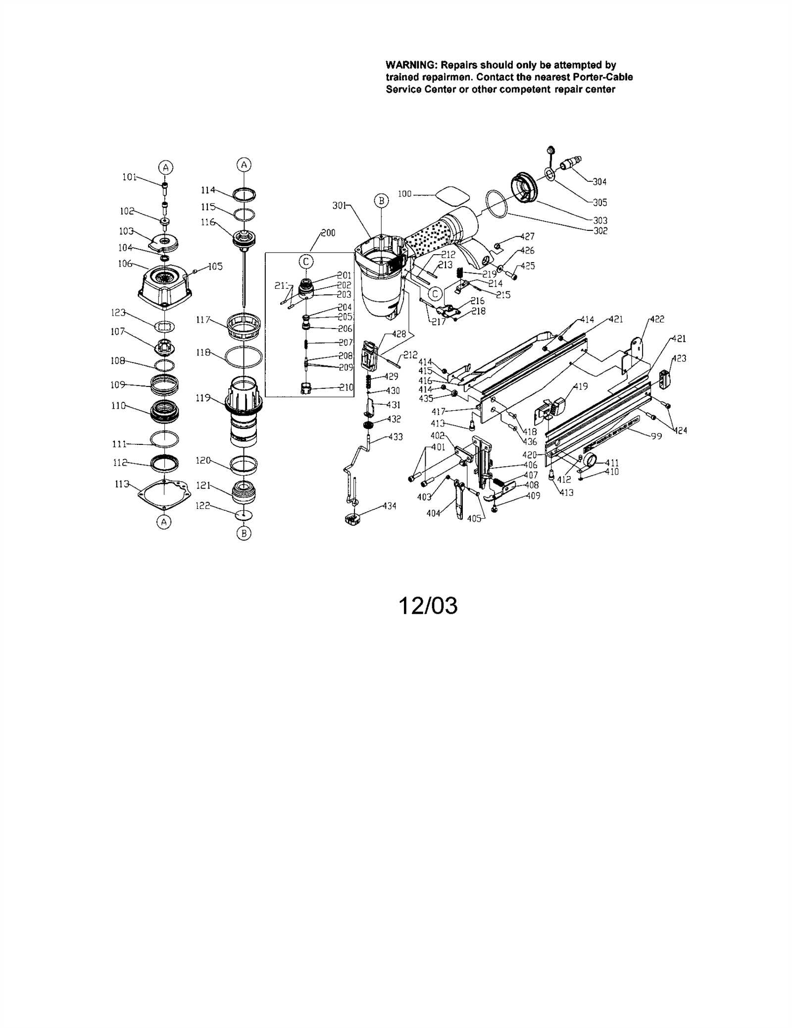
Understanding the Porter Cable FN250B Diagram
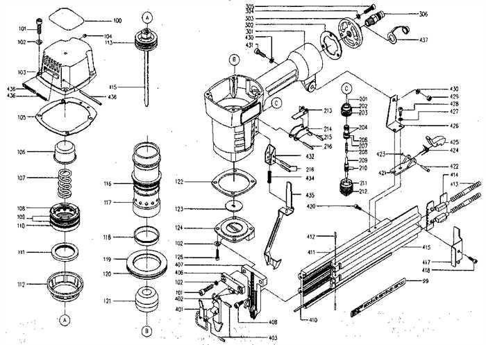
Every tool consists of a complex arrangement of components that work together to deliver optimal performance. To keep everything functioning properly, it is important to have a visual representation that clearly outlines the tool’s structure. Such an overview enables users to quickly identify the position and function of each element, allowing for easy troubleshooting and maintenance.
Familiarizing yourself with these illustrations can help you quickly detect which sections need attention. Whether you’re replacing a broken piece or cleaning certain areas, knowing where each part fits into the overall mechanism is invaluable. Proper understanding also aids in reducing the risk of improper reassembly, which can lead to further issues or malfunctions.
In this section, we will explore how these visuals serve as an essential tool for both professionals and DIY enthusiasts alike. With an accurate reference, you’ll be able to efficiently handle repairs and ensure the continued longevity of your equipment.
Identifying Key Components of the Tool

Understanding the core elements of any device is crucial for proper functioning and maintenance. Each tool is made up of various key components that work together to achieve the desired result. Identifying these parts is the first step in diagnosing problems or performing repairs effectively.
Main Functional Parts
The primary components of a tool are typically responsible for its basic operations. These parts include mechanisms that facilitate movement, pressure, or other essential actions. Recognizing these will help you understand the tool’s overall functionality and how it performs its tasks.
Support and Auxiliary Elements

In addition to the main parts, there are often supporting components that enhance efficiency, such as safety features or mechanisms that aid in smooth operation. Identifying these auxiliary elements is equally important, as they play a significant role in maintaining the tool’s performance and user safety.
How to Use the Parts Diagram for Repairs

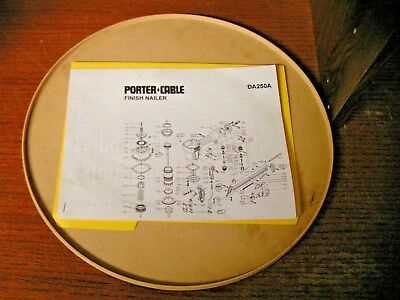
When performing maintenance or repairs on your tool, having a clear visual reference can greatly simplify the process. By using a detailed illustration of the tool’s internal structure, you can easily locate specific components that may need attention. This guide will show you how to make the most of such resources to ensure quick and accurate repairs.
The first step is to carefully examine the diagram, noting the position and function of each individual part. Once you’ve identified the component in question, compare it with the physical tool to check for wear, damage, or misalignment. This approach ensures you address the root cause of any issues rather than simply replacing parts at random.
Using this visual guide will help you save time by allowing you to focus on the necessary repairs while avoiding unnecessary disassembly. Whether you’re fixing a malfunction or performing routine maintenance, a clear reference can streamline the entire process.