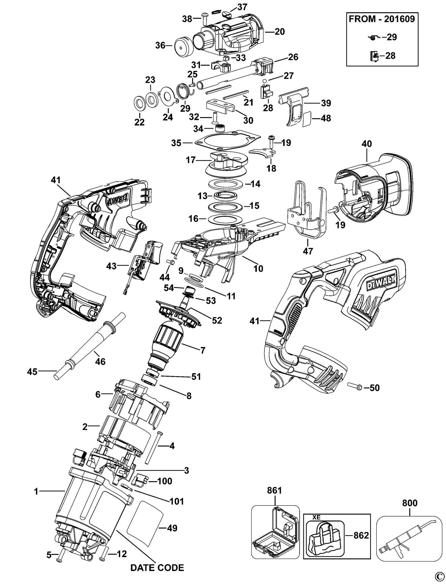
When maintaining or repairing any machinery, understanding how its components are organized is essential. A detailed view of the inner workings allows for efficient troubleshooting and replacement of individual elements.
In this section, we explore a clear and structured representation of the tool’s key components. This will help you identify each piece, its role in the system, and how it interacts with other parts for optimal performance.
Knowing the layout and functionality of each element can save you time and prevent costly repairs. By gaining a deeper understanding, you can make informed decisions about maintenance and ensure your tool operates smoothly.
Understanding the Dw708 Parts Layout
Having a clear understanding of the arrangement and functionality of individual components within a tool is essential for efficient usage and maintenance. This insight allows you to identify specific elements easily, ensuring proper care and troubleshooting when necessary.
Key Components Overview
Every tool is made up of several integral sections that work together to perform its function. Recognizing these components helps in understanding how each one contributes to the overall operation. Whether you are assembling or disassembling, identifying these sections is the first step towards effective handling.
How Components Interact
Understanding the relationship between each element is crucial. Some parts are interdependent, meaning a failure in one could affect the performance of others. By knowing how the various sections interact, you can better prevent issues and identify the root cause of any malfunction.
How to Read the Dw708 Diagram
Interpreting a technical illustration of a tool’s internal structure is essential for identifying components and understanding their assembly. A well-detailed visual guide can make it easier to pinpoint each part’s location and role, facilitating efficient repairs or maintenance.
Start by familiarizing yourself with the layout. The diagram usually arranges elements in a logical flow, showing how they connect and interact. Each part will be labeled, often with a number or code, allowing you to match it with specific descriptions or replacement guides.
It’s important to pay attention to the orientation and scaling of the image. Sometimes, components are displayed in exploded views to give you a better understanding of how they fit together. This can be especially helpful when dealing with complex assemblies or intricate mechanisms.
Common Parts and Their Functions
Each tool is composed of various essential elements, each serving a specific purpose to ensure proper functionality. Understanding the role of each part helps maintain efficiency and allows for quick identification during repairs or upgrades.
For example, the motor is often the primary component, responsible for driving the mechanism and generating power. Alongside it, the gears facilitate smooth movement and transfer of energy, enabling the tool to function as intended.
Other crucial elements include safety features, such as the trigger or switch, which control the operation. These parts help prevent misuse and ensure the tool functions only when intended. Additionally, supports and housings protect the internal components from damage and provide structural integrity to the overall unit.