Maintaining complex machinery requires a clear understanding of its various components and how they work together. A comprehensive guide can help you navigate through the different elements, ensuring proper upkeep and troubleshooting. When a machine starts malfunctioning, identifying the right part becomes essential for repairs and optimal performance.
Knowing how to interpret detailed illustrations of the internal structure can save time and effort during maintenance. These visual guides show where each element fits into the whole system, making it easier to spot potential issues. Accurate identification of the pieces is key to avoiding unnecessary repairs and improving overall efficiency.
Whether you’re a seasoned technician or a DIY enthusiast, mastering the layout of the device ensures that you can perform repairs with confidence. Being familiar with the assembly and functionality of each individual part will help extend the machine’s lifespan and enhance its performance.
Understanding Predator Auger 63022 Components
Each machine consists of several integral elements that work in harmony to perform its intended function. Familiarizing yourself with these components allows for a better grasp of the overall system and its maintenance needs. Identifying individual sections and their roles is essential when performing repairs or upgrades to ensure everything is operating at peak efficiency.
Key Elements of the Machine

The equipment is made up of various mechanical pieces, each serving a distinct purpose. From the motor to the auxiliary components, every section contributes to the machine’s ability to function smoothly. Recognizing the role of each part helps to diagnose potential failures and address them quickly, minimizing downtime.
Assembly and Integration
The assembly of these components is crucial for the machine’s overall performance. Understanding how different parts connect and interact with one another provides insight into common issues and how they can be resolved. Regular inspection and proper reassembly can prevent malfunctioning, ensuring that the machine continues to operate reliably over time.
How to Read the Parts Diagram
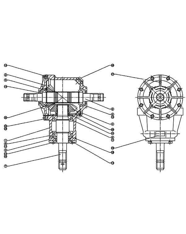
Interpreting visual representations of equipment components is a crucial skill for anyone working with mechanical systems. These illustrations provide a clear overview of the internal structure, showing how individual elements fit together. Understanding the layout of these images ensures that you can accurately identify each part and its function, leading to more efficient troubleshooting and repair.
Interpreting Symbols and Labels
Most diagrams use standardized symbols and labels to represent different elements. Each symbol corresponds to a specific component, and the labels often include part numbers, sizes, or additional details. Recognizing these symbols helps you navigate the diagram and locate the exact piece you need to examine or replace. Pay attention to any annotations, as they can provide extra context about assembly or maintenance instructions.
Following the Assembly Flow
Diagrams often depict the parts in a logical order that mirrors the assembly or operational flow of the system. By following this sequence, you can understand how each piece interacts with the others. This step-by-step breakdown helps in identifying where problems might arise and which areas require attention. Understanding the overall assembly process is key to performing repairs efficiently and avoiding mistakes.
Common Issues with Predator Auger Parts
When dealing with complex machinery, certain issues tend to arise more frequently than others. Understanding these common problems can help you quickly diagnose and fix issues before they escalate. Regular maintenance and prompt attention to recurring malfunctions are essential for keeping the equipment in good working condition.
Worn-out Components
One of the most common issues is the wear and tear of key mechanical elements. With regular use, certain parts can become damaged or degraded, affecting performance. Friction and constant motion can lead to parts losing their efficiency or failing entirely. Keeping an eye on these components and replacing them when necessary helps avoid unexpected breakdowns.
Assembly Misalignments
Another issue that often arises is improper alignment during assembly. If the components are not positioned correctly, it can cause strain on the system, leading to reduced efficiency or even system failure. Ensuring proper assembly and reassembling components as per the original layout can resolve these issues, ensuring smooth operation.