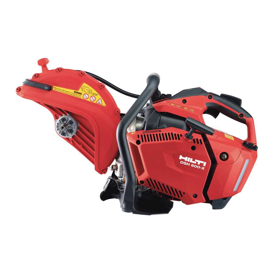
When working with complex machinery, having a clear understanding of the individual components is crucial for effective operation and maintenance. This section offers insights into the assembly structure, helping users identify key elements that ensure smooth functionality. Whether you’re a seasoned professional or a beginner, knowing how to manage the various parts of a tool can significantly improve its performance and longevity.
Identifying each component is the first step in mastering the equipment. A detailed overview of the assembly allows users to easily spot potential issues, perform troubleshooting, and replace worn-out elements. Understanding the layout of each section helps to streamline repairs and maintenance, making the entire process more efficient.
Moreover, the ability to interpret assembly guides enhances the overall user experience. By familiarizing yourself with the machine’s construction, you can ensure proper usage and avoid costly repairs. Whether it’s for daily use or specific projects, knowing the intricacies of your equipment can lead to better results and longer service life.
Understanding the Assembly Components

Every tool is made up of multiple individual elements that work together to provide its full functionality. Recognizing and understanding these elements is key to ensuring proper operation, maintenance, and repairs. Each component plays a unique role, contributing to the overall performance and durability of the equipment. Familiarity with how these parts interact with one another can help identify issues early and prevent costly repairs.
To get the most out of your machine, it’s important to understand how the core sections are structured and their specific functions. The assembly includes vital pieces such as the power source, mechanisms for movement, and safety features. By knowing the purpose of each section, users can better troubleshoot problems and optimize tool performance.
Additionally, identifying the right components for replacements and upgrades can prolong the lifespan of the tool. Recognizing the critical parts that require routine attention ensures that the machine continues to function smoothly over time. With the right knowledge, managing the equipment becomes more efficient and cost-effective.
How to Read the Assembly Layout
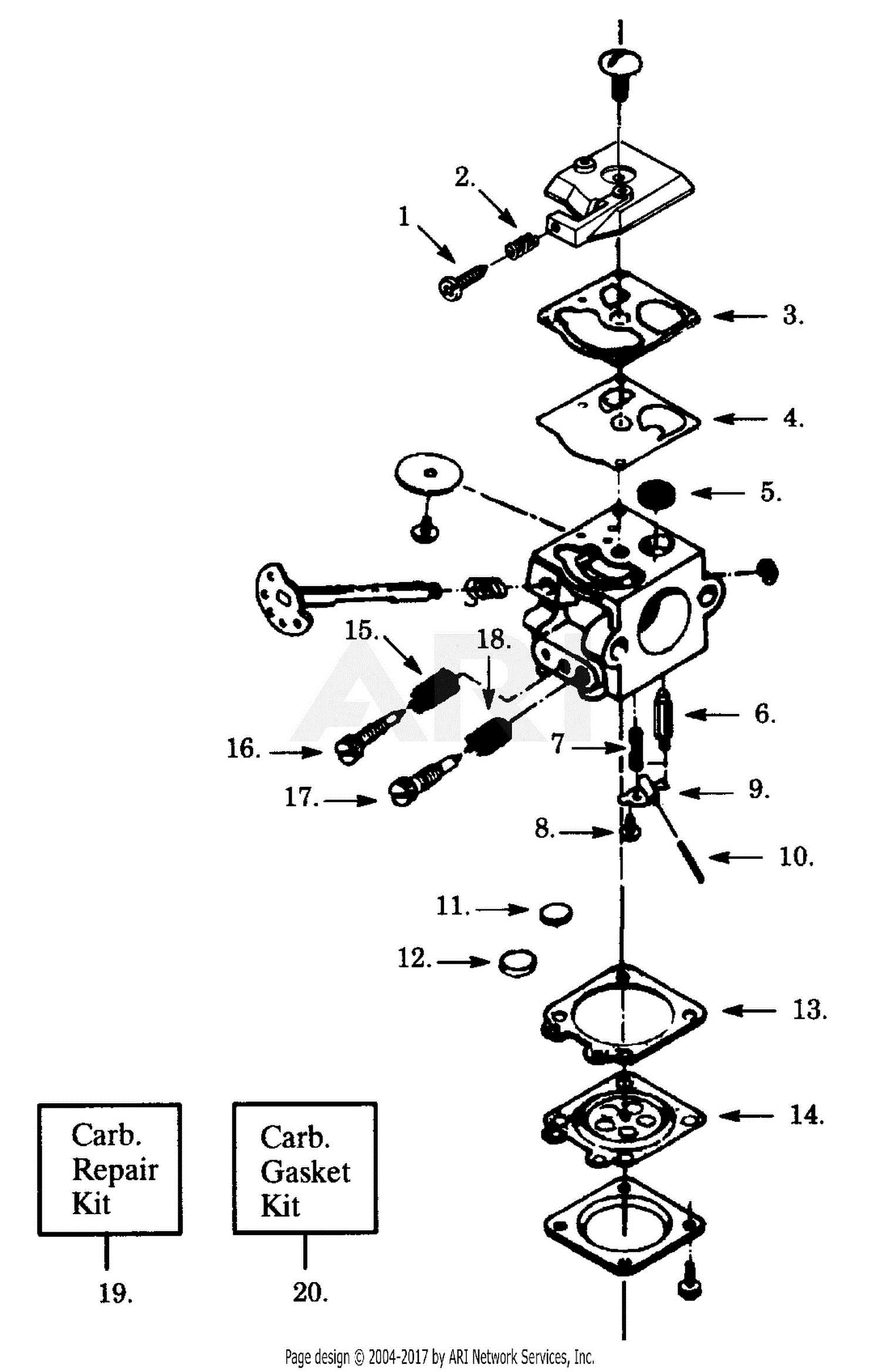
Understanding how to interpret a machine’s assembly layout is essential for effective troubleshooting and maintenance. These layouts offer a visual representation of how individual components fit together and interact. Each part is labeled, allowing users to easily identify the specific components they need to work with. Knowing how to read these layouts ensures that you can follow the correct procedures for repairs, replacements, or upgrades.
The layout typically includes clear labels and numbering systems to distinguish between various sections of the tool. Arrows or lines may be used to indicate how the pieces connect, making it easier to visualize the tool’s overall structure. Familiarizing yourself with these symbols and labels helps speed up the repair process by pointing out the exact location of each part.
By mastering the interpretation of these layouts, users can become more self-sufficient when maintaining or fixing their equipment. This understanding also aids in ordering the correct replacement parts, ensuring compatibility and efficiency. In turn, this knowledge can prevent unnecessary downtime and enhance the longevity of the tool.
Common Issues and Part Replacements
Over time, machinery can experience wear and tear, leading to specific issues that affect performance. Identifying these common problems early is essential for preventing further damage. Many of these issues are related to specific components, which may need to be replaced to restore the tool’s functionality. By understanding the typical faults and knowing when to replace certain elements, users can maintain optimal operation and extend the life of their equipment.
Frequent Problems in Tools

One of the most common issues involves the motor, where overheating or electrical malfunctions can significantly reduce performance. Another frequent problem is the wear of moving parts, such as the drive mechanism or the cutting blade, which can become dull or damaged with extended use. Additionally, parts that are exposed to harsh conditions, such as dust or moisture, can deteriorate faster and require timely replacement.
When to Replace Components
Knowing when to replace a component is critical to avoid compromising the overall performance. If a part shows signs of damage, such as cracks, rust, or unusual wear, it is time to replace it. Regularly checking and maintaining the tool can help prevent these issues from becoming major setbacks. Replacing worn-out components quickly ensures that the tool continues to perform efficiently, minimizing downtime and maximizing productivity.