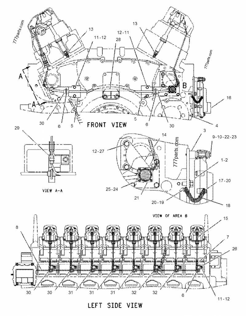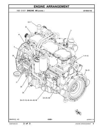
Understanding the internal structure of heavy machinery is essential for anyone involved in maintenance or repair. A clear and detailed representation of these mechanical systems can greatly improve the efficiency of servicing and troubleshooting. Knowing how each element works together ensures smoother operations and reduces downtime.
In this guide, we will explore the key components of large-scale mechanical systems. By looking at the visual schematics, you’ll gain a better understanding of how each part interacts within the larger machine framework. Whether you’re a technician or simply interested in machine design, this knowledge will help you navigate complex systems with ease.
Understanding the Machine Components
To effectively manage and maintain heavy machinery, it’s essential to have a comprehensive understanding of the key components that make up the system. These elements, working in unison, form the backbone of any powerful mechanical setup, driving performance and ensuring reliability. A solid grasp of these components helps technicians identify potential issues and address them proactively.
Each critical element, from the power transmission to the auxiliary systems, plays a vital role in the overall function. Knowing how these systems interconnect and influence each other is crucial for optimizing performance. Detailed schematics allow professionals to visualize how each part contributes to the machine’s operation, making maintenance and repairs more efficient.
Key Parts in a Mechanical System Layout

Identifying the essential components within a complex system is crucial for understanding its function and ensuring effective maintenance. These primary elements are the building blocks that contribute to the overall performance and longevity of the machinery. Each part is designed to perform a specific role, and its proper operation is essential for the seamless functioning of the whole system.
Some of the most critical components include those responsible for power generation, transmission, and cooling. These elements interact closely, and any malfunction can have a cascading effect on the overall operation. By closely examining the layout, one can better understand how these individual parts contribute to the system’s efficiency and reliability.
How to Read Mechanical System Schematics

Interpreting technical schematics is essential for anyone involved in maintaining or repairing complex machinery. These visual representations provide an overview of how each component fits into the larger system, showing connections and interactions between parts. Understanding these layouts allows technicians to diagnose problems quickly and make precise adjustments during maintenance.
When reading such schematics, focus on understanding the symbols used to represent each component. Typically, these diagrams will include lines to show connections, labels to identify parts, and arrows to indicate the flow of power or fluids. Familiarizing yourself with these conventions is key to navigating the layout and using it effectively during troubleshooting or repair tasks.