Maintaining outdoor machinery is essential for ensuring long-term performance and efficiency. Understanding the different components that make up your equipment helps identify potential issues and streamline repair efforts. Whether you are dealing with common wear and tear or specific mechanical faults, having a clear overview of how all the parts fit together can save time and reduce unnecessary repairs.
Repairing and troubleshooting can often seem daunting, but with the right knowledge, the process becomes straightforward. Knowing the correct terminology and the layout of the components provides valuable insight into each machine’s function. By following a detailed map of the components, you can approach any maintenance task with confidence, improving the longevity of your equipment.
In this guide, we’ll explore the essential components of your equipment and how to use a visual reference to troubleshoot issues effectively. A clear understanding of each element will allow for precise repairs, ensuring your machine operates smoothly season after season.
Understanding the Lawn Equipment Assembly
Each piece of outdoor machinery consists of multiple interconnected elements designed to work in harmony. The layout of these components plays a crucial role in the overall functionality, ensuring smooth operation and durability. Whether you’re performing routine checks or handling repairs, knowing the structure and interrelations of the assembly is key to effective maintenance.
The system is engineered to offer a balance between efficiency and power. From the cutting mechanism to the drive system, each part is designed to contribute to the machine’s overall performance. Familiarizing yourself with how each component supports the other will help when diagnosing issues and selecting the correct replacement pieces.
In the following sections, we’ll break down the components and their functions, giving you the knowledge to properly manage and care for your equipment. Understanding the assembly and its specific parts will allow you to make more informed decisions when performing maintenance tasks, ensuring optimal performance over time.
Key Components of the 54 Inch Mower
When it comes to maintaining outdoor equipment, understanding the key components is essential for efficient troubleshooting and repairs. The functionality of these systems relies on several interconnected parts that each serve a specific role. A thorough grasp of these elements helps in diagnosing issues and ensuring long-term performance.
Essential Components
The following elements are critical to the operation and efficiency of the machine:
- Cutting Blades – These are responsible for the primary function of trimming grass and vegetation.
- Spindles – These components house the bearings and help rotate the blades efficiently.
- Belts – Power transmission belts drive the motion of the blades and other moving parts.
- Pulley System – The pulleys direct the movement and help transfer power from the engine to the blades.
- Drive Mechanism – This system controls the movement of the entire machine, offering forward and reverse movement capabilities.
Supporting Parts
In addition to the core components, several supporting parts contribute to overall functionality:
- Frame – Provides structural support for the entire system, holding all parts together.
- Wheels and Axles – These elements enable mobility and provide balance during operation.
- Engine – Powers the entire system, providing the energy needed for movement and operation.
How to Use the Parts Diagram for Repairs
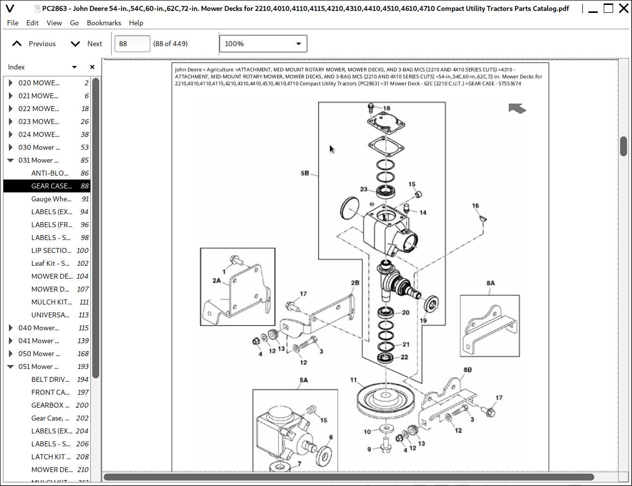
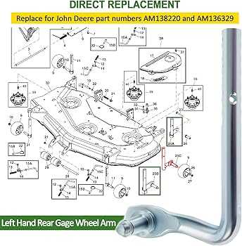
Utilizing a visual representation of the equipment’s components is an invaluable tool for performing repairs and replacements. Understanding how each element fits into the overall system allows for efficient troubleshooting and ensures that the correct parts are used for maintenance tasks. This guide will walk you through how to effectively interpret and use a visual reference for your repairs.
Step-by-Step Approach

When using a schematic for repairs, follow these steps to ensure a smooth process:
- Identify the Problem – Before referencing the visual, make sure you have a clear understanding of the issue you’re addressing.
- Locate the Relevant Section – The schematic will often be divided into sections. Find the area that corresponds to the malfunctioning component.
- Match Components with Visuals – Ensure the parts in the diagram match the actual components on your equipment to avoid confusion.
- Follow the Repair Steps – Use the diagram to guide you through the disassembly and reassembly process, ensuring each part is correctly positioned.
Common Mistakes to Avoid

While the visual reference is a helpful tool, avoid these common errors:
- Rushing the Process – Take your time to carefully inspect and understand each component to prevent mistakes.
- Overlooking Small Details – Even small components can be critical, so don’t skip over any parts when referencing the diagram.
- Using Incorrect Replacements – Always ensure the replacements match the specifications outlined in the visual guide.