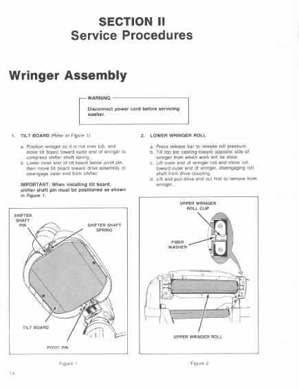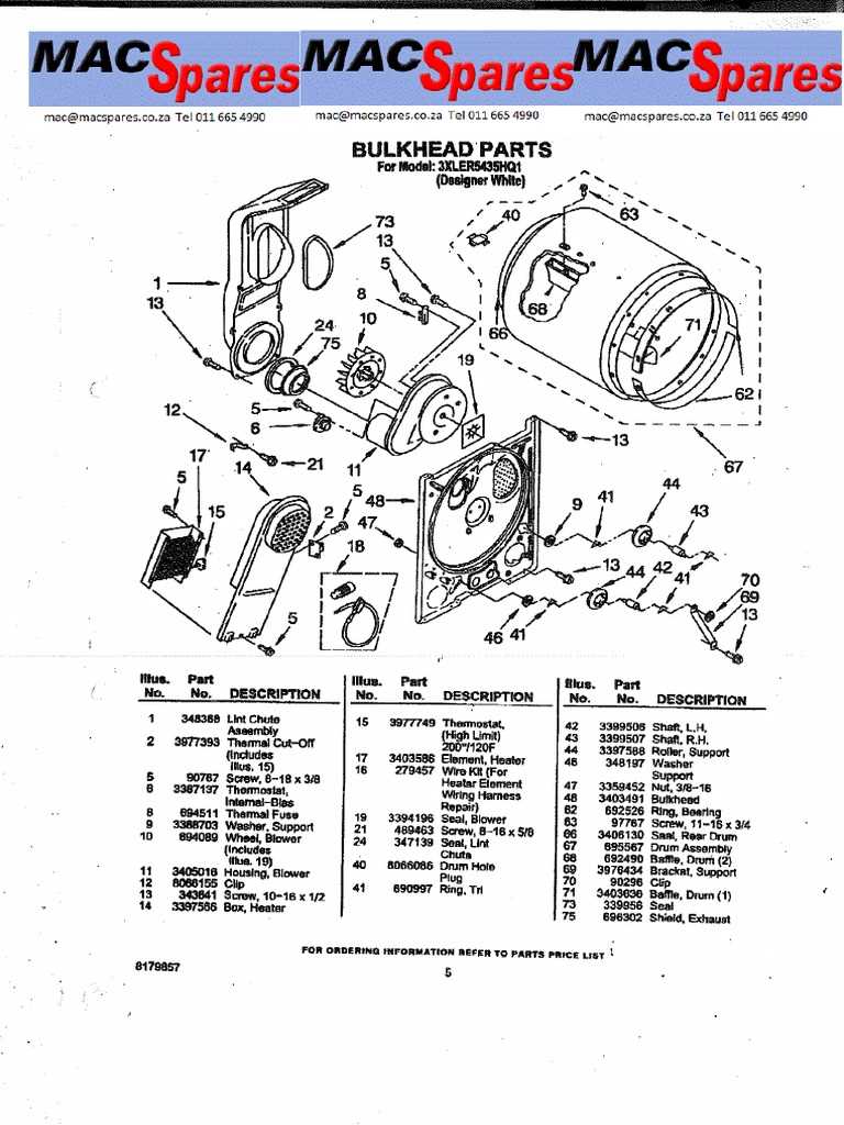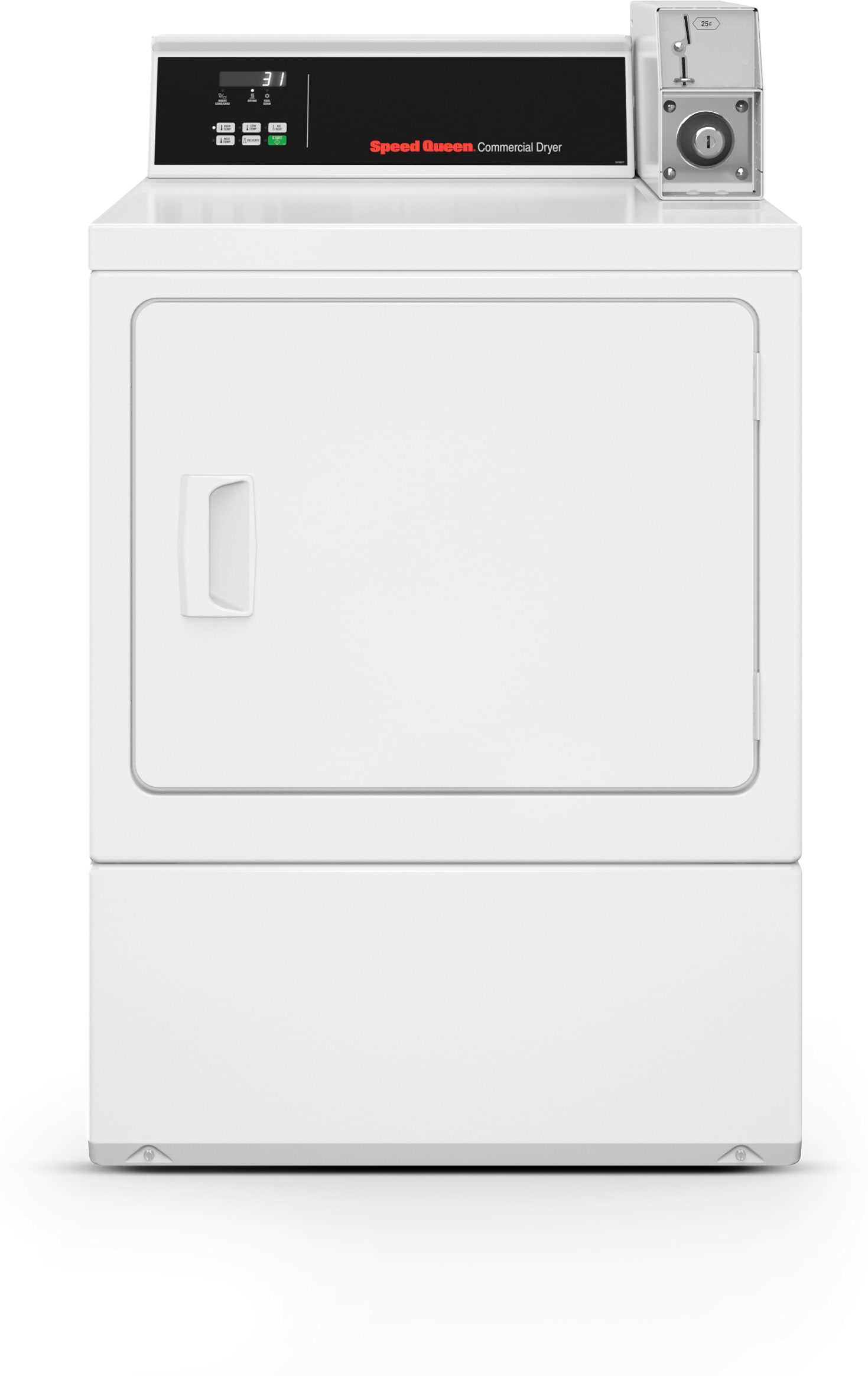
When it comes to maintaining and repairing heavy-duty machines, having a clear view of the internal structure is essential. Knowing where each element is located and how they interact can save time and effort during troubleshooting. Understanding the layout of different components ensures smooth repairs and better performance for the equipment in use.
Manuals and visual guides play a crucial role in identifying parts and their specific functions. These resources help users recognize the placement of various mechanisms and how to address common malfunctions. By studying the layout, even beginners can gain a deeper understanding of how things work and avoid costly mistakes.
Whether you are a professional technician or a business owner maintaining their machines, learning to interpret these visual representations will enhance your ability to perform repairs with accuracy. It also empowers users to keep their systems running optimally without the need for constant expert assistance.
Understanding Speed Queen Washer Parts
Every machine consists of multiple interconnected components, each playing a crucial role in its overall functionality. Recognizing how these elements work together is essential for anyone responsible for maintaining or repairing the equipment. By familiarizing yourself with the specific components and their placement, you can more easily diagnose issues and implement solutions.
The mechanical and electrical systems within these devices often include gears, belts, sensors, and control boards. Each of these elements has a unique function, and understanding their purpose helps in troubleshooting common malfunctions. A proper understanding allows users to identify where problems might arise, whether it’s from wear and tear or misalignment.
For effective maintenance, it is important to know how to access and replace these key components. With knowledge of the device’s structure, you can avoid unnecessary disassembly and ensure efficient repairs. The key to maximizing performance lies in understanding the inner workings and addressing issues before they become significant obstacles.
How to Read Speed Queen Diagrams
Understanding technical illustrations is key when dealing with any mechanical system. These visual tools offer a detailed view of the internal structure, making it easier to identify components and their relationships. To make the most of these resources, it’s essential to know how to interpret the symbols, lines, and connections represented in the images.
Labels and annotations are often used to indicate specific parts and their functions. Pay close attention to these markers, as they provide critical information about the role of each component within the system. Additionally, some diagrams may include color-coding or different line styles to differentiate between various systems or connections.
Familiarizing yourself with common conventions used in these illustrations will improve your ability to follow the layout. By practicing with a few examples, you can quickly learn how to pinpoint problems and understand the structure of the machine. These visual guides are invaluable for anyone looking to repair or maintain complex systems accurately and efficiently.
Common Speed Queen Washer Issues
Like any heavy-duty equipment, these machines can experience a variety of malfunctions over time. Understanding the most common issues can help users identify problems early and take preventive measures. Troubleshooting these devices often requires recognizing patterns in the way the machine operates and pinpointing the faulty components.
Mechanical Problems

- Failure to start due to faulty connections or malfunctioning motors
- Unusual noises caused by worn-out belts, pulleys, or bearings
- Imbalance during the spin cycle, often linked to damaged drum components
Electrical and Control Issues

- Inconsistent or non-responsive control panels, typically caused by damaged wiring or faulty circuit boards
- Water temperature irregularities due to malfunctioning thermostats or sensors
- Power supply interruptions, which may result from broken fuses or electrical connections
Recognizing these typical problems early on allows for quicker and more efficient repairs, minimizing downtime and ensuring the system continues to function properly. Regular maintenance and inspection are key to extending the lifespan of the equipment and avoiding major failures.