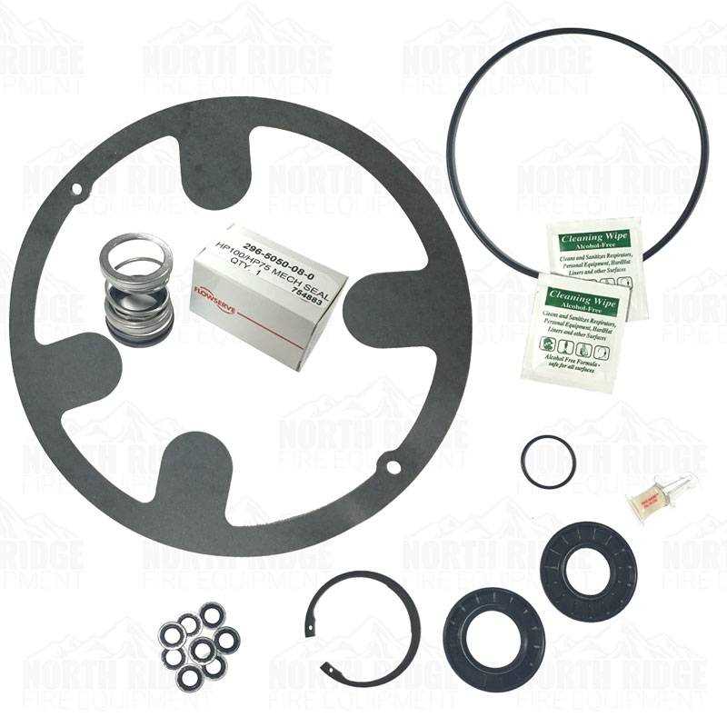
In the world of firefighting, precision and reliability are paramount. To ensure smooth operation, it is crucial to understand the essential elements that make up the machinery used in emergency situations. Each piece plays a significant role in the overall functioning and efficiency of the system.
Understanding how these elements fit together is vital for maintenance, troubleshooting, and repairs. Knowing the layout of each component allows technicians to identify potential issues quickly and keep everything running optimally. This guide provides an overview of how these parts interact within the system.
By mastering the technical aspects and familiarizing oneself with the configuration of the equipment, both operators and maintenance personnel can enhance safety and performance, ensuring readiness when it matters most.
Understanding Hale Pump Components
In any firefighting system, the interaction of various mechanical and hydraulic elements is crucial for optimal performance. These systems consist of multiple components that work together to deliver water or other fluids under pressure. Each part has a specific role that ensures the efficiency and reliability of the overall equipment during emergency situations.
Key Components and Their Functions
The core components include elements that control the flow, pressure, and distribution of the fluid. From the intake to the outlet, each segment is carefully designed to withstand the intense demands of firefighting tasks. The intake section regulates the entry of water, while the outlet controls its discharge. Other key elements, such as valves, seals, and gauges, help monitor and adjust the system’s performance to maintain constant pressure and flow.
Importance of Proper Maintenance
Regular maintenance and proper inspection of these critical elements are vital to ensure the equipment operates smoothly when needed. Understanding the functions and layout of each part allows operators to identify potential issues before they lead to equipment failure. Timely repairs and part replacements are essential for maintaining the safety and readiness of the system during emergencies.
How to Read a Hale Pump Diagram
Understanding technical schematics is essential for troubleshooting and repairing complex machinery. A well-designed blueprint provides a detailed representation of the system’s structure, highlighting the interconnections between components. By learning to interpret these schematics, technicians and operators can quickly identify issues and make informed decisions during maintenance.
Interpreting Symbols and Labels
Each element in the system is represented by specific symbols, which correspond to real-world components. These symbols are standardized and are crucial for understanding the layout and function of each part. Labels alongside these symbols provide additional information, such as part numbers, flow directions, and pressure readings, enabling precise identification of each component’s role within the system.
Following the Flow Paths
Flow paths, often depicted by arrows, show the movement of fluids through the system. Understanding these pathways is essential for diagnosing performance issues, such as reduced pressure or flow. By tracing the fluid route from intake to discharge, operators can pinpoint potential blockages, leaks, or inefficiencies that may affect the overall system’s performance.
Common Issues with Hale Pump Parts
Like any mechanical system, firefighting equipment is susceptible to wear and tear over time. While regular maintenance can prevent many issues, certain problems are more common and require attention during operation. Understanding these common challenges can help identify potential failures early and ensure the system remains reliable when needed most.
One of the most frequent issues is reduced flow or pressure, often caused by clogs or blockages in the intake or discharge lines. This can occur if debris or sediment accumulates, obstructing the normal fluid flow. Another issue is valve malfunctions, where improper sealing or mechanical failure can lead to leaks or inconsistent pressure control, impacting performance. Additionally, damaged seals or gaskets are another common culprit, often leading to fluid leakage or loss of efficiency.
Keeping an eye on these typical problems and addressing them promptly can significantly extend the lifespan of the system. Regular inspections, cleaning, and timely part replacements can minimize downtime and ensure the equipment operates at peak capacity in critical situations.