When it comes to maintaining agricultural machinery, having a clear understanding of its internal structure is essential. A well-organized visual representation of a machine’s components can significantly simplify the repair and replacement process. By referring to a detailed chart, operators and mechanics can easily identify and address issues, ensuring the equipment runs smoothly for longer periods.
Proper identification of each element is crucial for selecting the right replacement parts, reducing the risk of mistakes, and improving efficiency in repair tasks. With the right visual aid, finding and fixing faulty components becomes a streamlined process, saving both time and effort.
Having access to an accurate and detailed schematic also helps prevent unnecessary damage to the machine. By understanding how different components interact and where they are located, maintenance becomes more precise, and the overall performance of the equipment can be optimized.
Understanding the Tractor Component Layout
Every piece of machinery relies on an intricate system of components working together to achieve optimal performance. A detailed visual representation allows for easy identification and a better understanding of how these elements are structured. Knowing the exact layout helps users quickly spot potential issues and simplify maintenance tasks, ensuring that everything functions efficiently and safely.
Key Elements to Look For

When examining the layout, it’s important to focus on critical sections such as the engine, transmission, and steering systems. Each of these areas has a set of interconnected parts that contribute to the machine’s overall function. Understanding where each part is located and how it connects to others makes troubleshooting easier and more accurate.
Benefits of Using Visual Aids
Utilizing a well-organized chart can save time and prevent errors during repair or replacement procedures. It ensures that technicians are replacing the correct components, preventing mistakes and unnecessary costs. Furthermore, knowing how each part fits into the larger system allows for more informed decisions when making repairs or upgrades.
How to Identify Key Components
Identifying the crucial elements of machinery is essential for effective maintenance and repair. A thorough understanding of each component’s function and location ensures that you can troubleshoot issues efficiently. By focusing on major sections of the equipment, you can quickly pinpoint areas that require attention, whether for routine servicing or more complex repairs.
Focus Areas to Start With
Begin by examining the most critical systems that drive the machine’s overall performance. These systems typically include:
- Engine – The heart of the machine, responsible for generating power.
- Transmission – Transfers power from the engine to the wheels or other driving mechanisms.
- Steering Mechanism – Allows the operator to control the direction of movement.
- Electrical System – Powers essential functions such as lights and control systems.
Using Visual Aids for Clarity
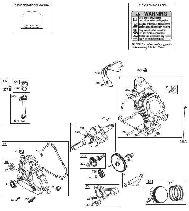
A clear and detailed reference guide can make the identification process much more straightforward. Look for diagrams or charts that label each key part, highlighting their connections and interactions. These visual tools will help you locate specific components and understand their roles within the larger system, making repair and maintenance tasks more manageable.
Common Issues and Replacement Tips
Every piece of machinery is subject to wear and tear, leading to frequent issues that need timely resolution. Recognizing these common problems early can prevent further damage and reduce repair costs. Knowing the typical challenges a machine faces helps users prepare for maintenance and ensures efficient repairs when needed.
Typical Problems to Watch For
Several issues frequently arise in machines, including:
- Engine Misfire – Often caused by worn spark plugs or fuel system clogs, affecting overall performance.
- Hydraulic Failures – Leaks or low fluid levels in the hydraulic system can reduce lifting or pushing power.
- Clogged Air Filters – A blocked air filter can hinder airflow to the engine, causing it to lose power or overheat.
- Steering Malfunctions – Issues with steering components may result from worn joints or low fluid levels in the steering system.
Replacement and Repair Tips

When replacing faulty components, it’s essential to select high-quality parts to avoid future breakdowns. Follow these tips to ensure efficient replacements:
- Always use OEM or recommended components to maintain performance standards.
- Perform regular inspections to catch issues before they escalate.
- Consult user manuals for specific replacement guidelines and torque specifications.
- Keep a well-stocked inventory of essential parts for quick fixes during busy seasons.