When working with any machine, knowing its individual components and how they fit together is essential for maintaining its efficiency and ensuring its longevity. Understanding how each part functions can help prevent common issues and make the repair or replacement process easier when needed.
In this section, we will break down the different parts of a commonly used gardening tool, offering insight into its construction. With clear identification and labeling of key elements, users can gain a deeper understanding of the essential pieces that contribute to the overall performance of the equipment.
Having access to this knowledge allows for quicker troubleshooting, reducing downtime and providing better solutions for repair or upgrades. This guide aims to simplify the process by presenting a clear view of each element, ensuring that users can confidently manage their maintenance tasks.
Understanding the Equipment Breakdown
Every complex tool consists of several key components that work together to ensure proper function. Recognizing each part’s role within the machine helps users perform maintenance tasks more effectively, allowing for smoother operation and fewer problems in the long term. By understanding the construction and layout of each section, users can quickly identify issues and take appropriate action.
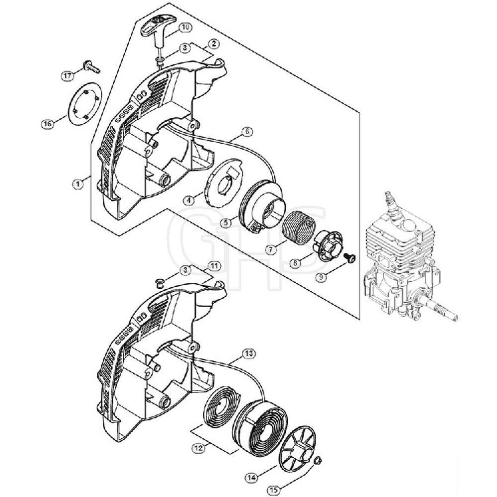
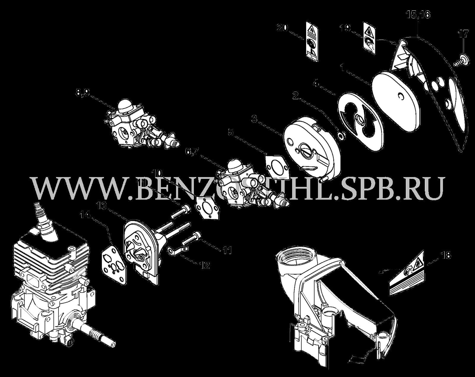
When looking at a detailed illustration, it’s important to focus on the relationship between the various elements. The layout provides a clear visual representation, helping to identify each item and understand how it contributes to the overall functionality. This approach is crucial for both routine maintenance and more in-depth repairs.
In addition to helping with repairs, a clear understanding of the machine’s components can improve the efficiency of any upgrades or customizations. Knowing how each section interacts allows for informed decisions when selecting replacements or enhancements, ensuring the tool performs optimally under different conditions.
How to Read the Equipment Layout
Understanding how to interpret a machine layout is essential for performing accurate maintenance or troubleshooting. The layout provides a visual map of all the components, offering clear guidance on where each part fits and how it functions within the overall system. Properly reading these illustrations can save time and reduce confusion when working on repairs.
Identifying Key Sections

Start by identifying the main sections of the layout, typically organized by the tool’s function or assembly. Each group of components is usually labeled or numbered, making it easy to find the relevant part when needed. Pay attention to any arrows or symbols that indicate connections or movements between elements.
Understanding Part Connections

Once the individual components are identified, focus on their connections. The layout often shows how parts are linked, whether by screws, bolts, or other fasteners. This understanding allows for easier disassembly and assembly, ensuring that parts are properly aligned during the repair process.
Common Replacement Components for the Equipment
Over time, certain components of any tool may experience wear and tear, requiring replacement to maintain optimal performance. Some elements are more prone to damage due to frequent use, making them essential to keep on hand for quick repairs. Knowing which parts commonly need replacing can help you plan ahead and ensure minimal downtime when the tool is in use.
Frequently replaced components often include those involved in high-stress areas, such as the cutting mechanism, drive shafts, and spark plugs. These parts play critical roles in the overall function of the tool, and ensuring they are in good condition will extend the tool’s lifespan. Regular checks can identify when these elements need to be replaced, preventing larger issues from arising.