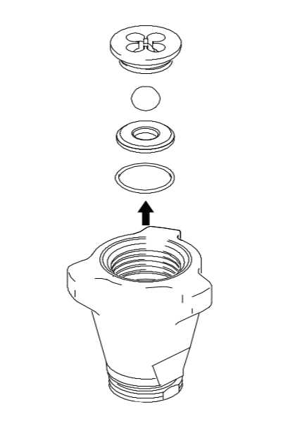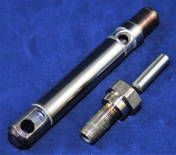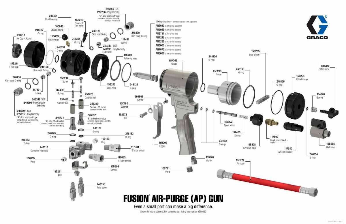
Understanding the structure and functionality of machinery is crucial for efficient operation and maintenance. When faced with complex equipment, a visual representation can greatly simplify the process of identifying and replacing parts. This section provides a detailed overview of how to interpret such illustrations, helping users identify essential components without confusion.
Effective maintenance relies on a clear understanding of each part’s role within the system. By using detailed schematics, users can easily locate the parts that require attention and avoid unnecessary steps during repairs. This guide emphasizes the importance of familiarizing oneself with these resources to ensure smooth and effective repairs.
Learning how to read these detailed resources enhances your ability to troubleshoot issues efficiently. With the right knowledge, even users with minimal technical experience can perform repairs confidently, ensuring that equipment runs optimally for longer periods.
Understanding Graco 490 Parts Diagram
Having a clear and organized visual guide to machinery components is essential for efficient troubleshooting and maintenance. Such a representation helps users understand the structure of their equipment, making it easier to identify specific sections that may require attention. By reviewing these illustrations, users can pinpoint critical elements and perform repairs or replacements accurately and swiftly.
Key Elements and Their Functions
Every component within a system serves a specific purpose, and understanding their individual roles is crucial for effective maintenance. These guides typically highlight important sections, such as valves, pistons, and seals, showing their exact placement within the machinery. Recognizing these parts allows for more precise interventions and helps prevent potential damage caused by incorrect handling.
Benefits of Using Visual Guides
Utilizing detailed visual resources greatly enhances the repair process. These guides eliminate ambiguity, ensuring that technicians can easily navigate through complex systems. By identifying and replacing the right parts, users can avoid time-consuming guesswork and minimize the risk of further issues, resulting in smoother operation and prolonged equipment lifespan.
Identifying Key Components of Graco 490
Accurate identification of crucial elements within machinery is essential for proper maintenance and repair. Understanding the function and placement of each key component allows users to work efficiently, ensuring minimal downtime and smooth operation. Recognizing these parts is especially important when dealing with complex systems that require specific interventions.
Essential Parts and Their Roles

Each part in a system plays a vital role in its overall functionality. For example, components such as pumps, valves, and seals are responsible for controlling the flow of material and maintaining pressure levels. Knowing where these parts are located and how they function together is important for diagnosing and solving performance issues.
Visual Cues for Quick Identification
Detailed schematics provide visual cues that make identifying critical components much easier. These illustrations allow users to locate parts quickly, avoiding confusion and ensuring that the right elements are addressed during repairs. By recognizing common shapes and sizes, technicians can efficiently pinpoint the areas that need attention, streamlining the repair process.
How to Use the Graco 490 Parts Diagram
Utilizing a visual guide for machine components allows users to navigate through complex systems with ease. By referencing these illustrations, users can accurately identify specific sections, making it simpler to perform repairs and maintenance tasks. Knowing how to effectively interpret these resources is essential for avoiding mistakes and ensuring a smooth repair process.
Step-by-Step Guide for Interpretation

Start by familiarizing yourself with the overall layout and organization of the visual guide. Each section typically represents a different part of the system, with labels or numbers indicating their respective locations. Begin by locating the area that needs attention and match it to the corresponding part on the schematic. Understanding these basic steps ensures efficient navigation through the guide.
Common Mistakes to Avoid
One of the most common errors when using visual guides is overlooking small details, such as part orientation or specific labels. Always double-check the placement of components and verify the information before proceeding with repairs. By paying attention to these details, you can prevent incorrect assembly or installation of parts, leading to a more effective repair process.