The inner workings of a power-producing system are complex and involve various interconnected elements that work in harmony. Each component plays a vital role in ensuring optimal performance and efficiency. Understanding these elements is crucial for anyone looking to grasp the fundamentals of mechanical power generation and the mechanics behind it.
Efficient operation relies heavily on the precise interaction of individual sections. From the intake to the exhaust, each element contributes to the overall functionality. These systems are engineered to withstand extreme conditions, making the understanding of their composition essential for maintenance and troubleshooting.
In this section, we will explore the key components and their functions, highlighting how each piece contributes to the overall operation. Whether you are a mechanic, engineer, or simply an enthusiast, grasping the design and operation of these systems will provide valuable insight into their reliability and efficiency.
Key Components of a Diesel Engine

The core of any power-producing system consists of several crucial elements, each designed to perform a specific function within the overall process. These components are responsible for converting fuel into mechanical energy, ensuring the system operates efficiently and reliably under various conditions. Understanding each part’s role helps in maintaining and troubleshooting the system effectively.
The combustion chamber, where the fuel is ignited, is one of the most vital sections. It works in conjunction with the intake and exhaust mechanisms to control airflow and expel gases after the combustion process. A well-designed combustion chamber ensures maximum fuel efficiency and power output.
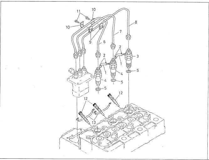
The fuel delivery system is another integral part, responsible for accurately supplying fuel to the combustion chamber. This system typically includes injectors and pumps, which control the fuel flow to achieve optimal performance. Alongside this, the lubrication system plays a critical role in reducing friction and wear on moving components, extending the system’s lifespan.
Other components, such as the cooling and electrical systems, help regulate temperature and ensure stable operation. The cooling system prevents overheating, while the electrical system powers the ignition and other key functions, such as sensors and control units. Each element is designed to work in tandem with the others, contributing to the smooth and efficient operation of the entire setup.
How Diesel Engine Parts Work Together

The efficient operation of a mechanical power system depends on the seamless interaction of its various components. Each element is designed to perform a specific task, yet they all rely on one another to maintain overall functionality. When each section operates in harmony, the system achieves its maximum potential for performance and durability.
Fuel delivery and air intake systems work closely to ensure the right mixture of air and fuel reaches the combustion area. The fuel injectors deliver precise amounts of fuel, while the intake valves regulate the flow of air necessary for the ignition process. Once the combustion takes place, the exhaust system ensures the efficient expulsion of gases, preventing any buildup that could disrupt the cycle.
The cooling and lubrication systems support the continuous operation by reducing heat buildup and friction. The cooling system circulates fluid to maintain optimal temperatures, preventing overheating, while the lubrication system minimizes wear and tear on the moving parts, allowing them to function smoothly over time.
Finally, the electrical components regulate the ignition process, ensuring that the correct timing and spark are provided for combustion. Sensors and control units monitor the performance of each system, adjusting parameters as needed to maintain efficiency and prevent malfunctions. Together, these systems create a balanced and synchronized process, resulting in a reliable and high-performance setup.
Common Diesel Engine Diagrams Explained

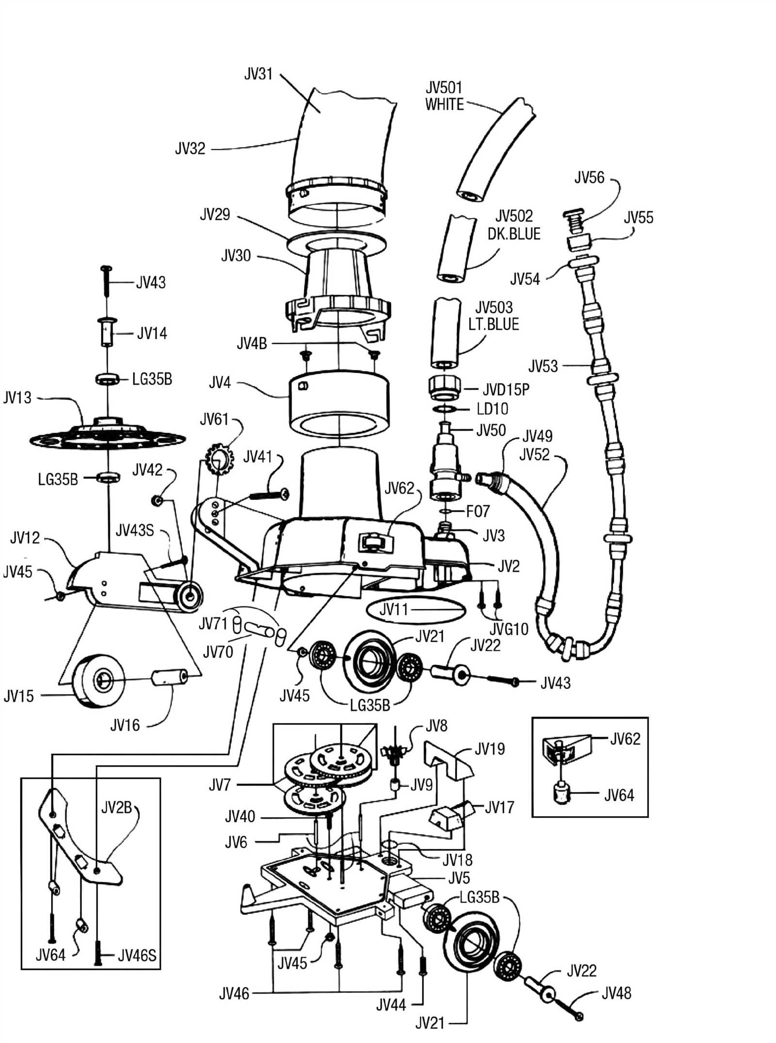
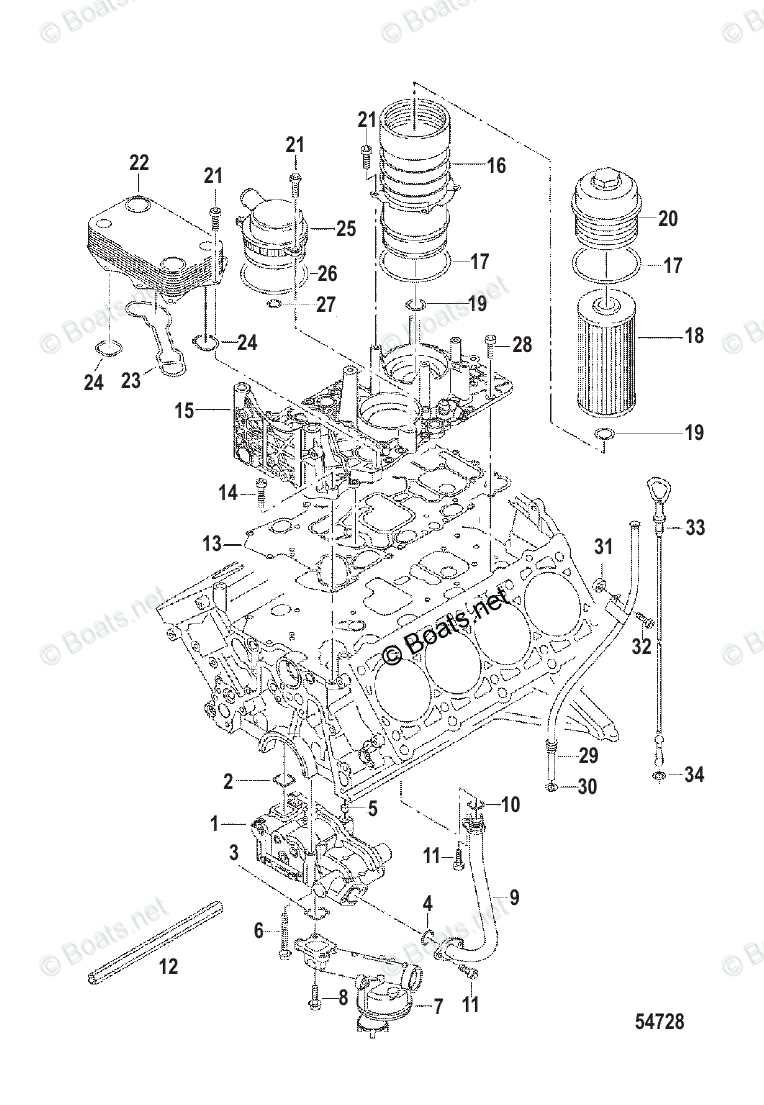
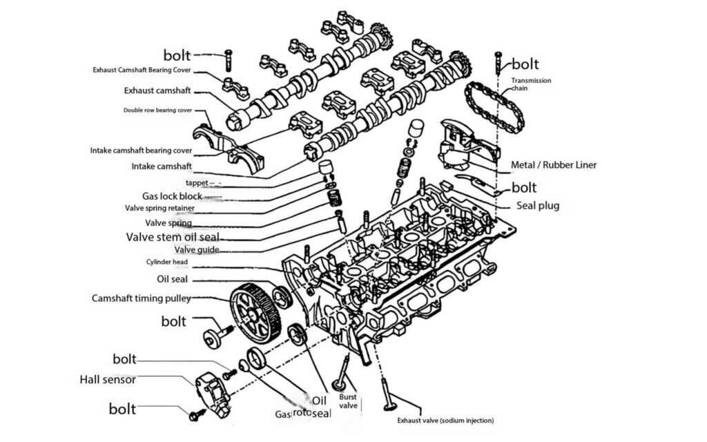
Visual representations of mechanical systems help break down complex processes into understandable parts. These illustrations provide a clear overview of how the various sections interact and contribute to the overall operation. By looking at these drawings, one can gain insights into the inner workings and the sequence of actions that take place within the system.
One of the most common types is the schematic layout, which shows the flow of energy through different components. These diagrams often highlight how fuel, air, and exhaust gases move through the system, detailing each component’s location and its role in the process. Understanding the flow allows for easier troubleshooting and maintenance, as any disruptions in the cycle can be identified quickly.
Another frequently used type is the cross-sectional view, which provides a detailed look inside the system. These diagrams cut through the structure to reveal how individual components, such as pistons, valves, and injectors, fit together and interact. This kind of representation is particularly useful for understanding the internal mechanics and the relative positioning of the parts.
Additionally, system flow charts are often used to depict the operational sequence, illustrating how different systems (cooling, lubrication, and fuel delivery) coordinate to maintain consistent performance. These charts emphasize the timing and interdependence of the actions required for efficient operation, showing how each system plays a role in the overall efficiency of the setup.