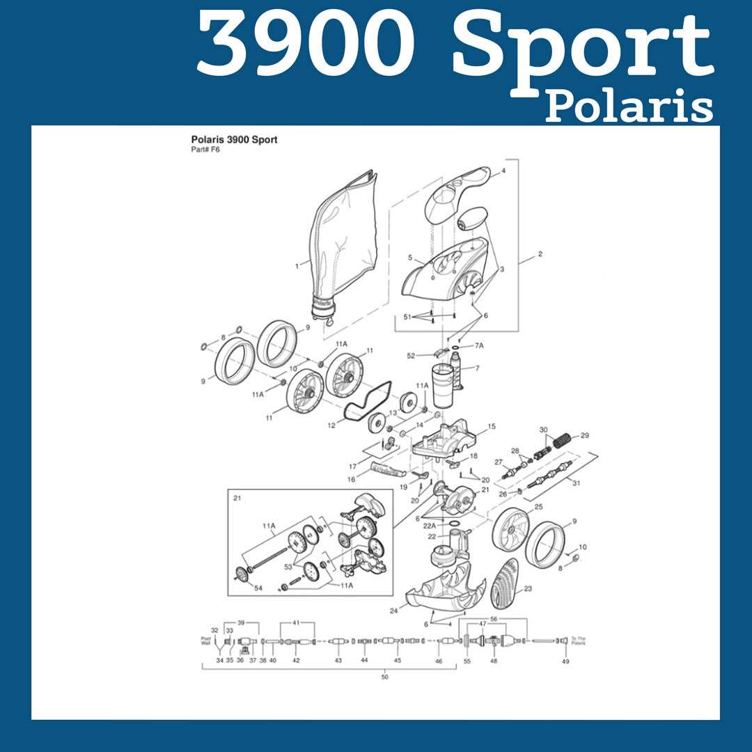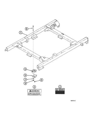
When it comes to efficient operation, understanding the individual elements of a system is crucial. Each component plays a vital role in ensuring optimal performance, and knowing their functions can help in troubleshooting and repairs. This section offers an in-depth look at the essential building blocks that make up the machinery, breaking down their purpose and how they interact with each other.
Proper knowledge of these components is not only important for repairs but also for ensuring longevity. By familiarizing yourself with the system’s layout and the connections between parts, you can effectively maintain it, avoiding costly mistakes and ensuring it runs smoothly for years to come.
Whether you’re looking to replace a malfunctioning element or simply want to understand your device better, this guide will provide the clarity you need to proceed with confidence.
Understanding the Key Components
Every mechanical system is composed of various elements that each serve a specific function. Understanding these individual components is essential for both operation and maintenance. A clear grasp of how each piece contributes to the overall efficiency of the device ensures better performance and easier troubleshooting.
Here’s an overview of the fundamental components typically found in such systems:
- Drive Mechanism – Responsible for powering movement, this component is at the heart of the system’s functionality.
- Control Unit – Manages the operation by coordinating various tasks and processes within the machinery.
- Power Supply – Provides the necessary energy for all system functions, making it one of the most critical parts to monitor.
- Sensors – Detect and relay important information about the system’s status and environment, enabling adjustments to be made for optimal functioning.
- Frame and Housing – Protects all internal elements while providing structural support to the entire system.
Each of these components is integral to the system’s ability to operate efficiently. Knowing their location and function makes maintenance tasks much easier and helps you identify potential issues quickly.
In the next section, we will explore how these components are organized and how to interpret their layout effectively.
Key Parts in the System
In any complex mechanical device, several essential elements work together to ensure smooth operation. These components are designed to support various functions, from movement to control, and each one plays a significant role in maintaining efficiency and performance. Understanding these key elements is vital for troubleshooting, repairs, and general maintenance.
Drive Mechanism is the core element that powers movement throughout the system. It is responsible for converting energy into mechanical motion, allowing the device to perform its intended functions.
Control Unit acts as the brain of the system, regulating and coordinating the actions of other components. It processes input from sensors and directs operations accordingly.
Energy Supply ensures that the entire system has the power it needs to function. This part is crucial, as any failure in the energy source can cause the system to malfunction or shut down completely.
Sensors are responsible for gathering data about the environment or system status. These readings allow the control unit to make adjustments to optimize performance, ensuring the system operates under ideal conditions.
Structural Framework serves as the foundation that holds all the other elements in place. This provides the necessary support and protection for the internal components, preventing damage from external forces.
Each of these critical parts is integral to the overall function of the system. A failure in one part can often lead to problems throughout the entire device, which is why understanding their individual roles is essential for proper maintenance.
Interpreting the layout of a mechanical system can be an essential skill for maintenance and repairs. A clear understanding of how various components are organized and connected allows for efficient troubleshooting and part identification. This section will guide you on how to analyze such layouts and extract the necessary information.
Identifying Key Elements
Each element in the layout is represented by symbols or shapes that indicate its function. For instance, mechanical parts might be depicted as boxes or circles, while connectors and wires are shown as lines. Understanding the meaning behind these symbols is the first step in making sense of the layout. It’s important to familiarize yourself with these common representations to avoid confusion during the analysis.
Interpreting Connections and Flow
The connections between components are usually depicted as lines or arrows, showing how energy or data flows through the system. Follow these lines carefully to understand the sequence of operations. This flow is essential in diagnosing issues, as a problem in one component can often disrupt the flow and cause a ripple effect throughout the system.
Once you’re comfortable identifying the symbols and interpreting the flow, you’ll be better equipped to troubleshoot and perform maintenance on the device. Understanding the layout is the key to efficient repair and part replacement, saving both time and effort.
Decoding the Blueprint
Understanding the layout of a system blueprint is crucial for anyone involved in maintenance, repair, or modification tasks. These blueprints provide a visual representation of how the components are organized and interact with each other. By carefully examining the blueprint, you can identify key parts, connections, and flows, which helps in diagnosing issues and planning repairs.
Recognizing Symbols and Notations

Blueprints often use standardized symbols to represent different parts of the system. These symbols can vary by manufacturer but generally follow certain conventions. For example, electrical components might be shown as specific icons, while mechanical parts may be represented by more abstract shapes. Familiarizing yourself with these symbols is the first step to accurately reading the blueprint.
Tracing the System Flow
The blueprint also illustrates how different components are connected and how energy, data, or fluids move through the system. Arrows, lines, and pathways indicate the flow between elements, showing how each part contributes to the overall function. Paying close attention to these connections is essential for understanding how the system operates as a whole, and it helps in pinpointing potential problem areas.
Once you become familiar with the symbols and flow, decoding the blueprint becomes a more intuitive process. This understanding will make it easier to perform repairs, replace damaged components, and maintain the system for optimal performance.
Proper maintenance is essential for ensuring the long-term functionality and reliability of any mechanical system. Regular upkeep not only enhances performance but also helps prevent costly repairs and replacements. In this section, we’ll explore key maintenance practices that can extend the life of your equipment and keep it running smoothly.
Routine checks and proactive measures are critical for preventing issues before they escalate. Here are some key areas to focus on:
| Maintenance Task | Frequency | Importance |
|---|---|---|
| Inspecting Mechanical Components | Monthly | Ensures all moving parts are functioning properly and reduces wear over time. |
| Cleaning and Lubrication | Quarterly | Prevents buildup of dirt and debris that can cause friction and damage to parts. |
| Checking Electrical Connections | Every 6 Months | Maintains a stable power flow and reduces the risk of electrical failures. |
| Replacing Worn Out Parts | As Needed | Prevents system failures and ensures optimal performance by replacing damaged components. |
By adhering to a consistent maintenance schedule and addressing potential issues promptly, you can significantly extend the lifespan of your equipment and keep it operating at peak efficiency.
Extending the Life of Your System
Maximizing the longevity of any system requires a combination of proactive care and consistent attention. By implementing effective strategies, you can ensure that your equipment continues to function optimally for many years. Regular upkeep, proper usage, and addressing issues promptly are key elements that contribute to prolonged performance.
One of the most important factors in extending the lifespan of your system is maintaining cleanliness. Dirt and debris can cause friction, wear, and damage to delicate parts, leading to malfunction. Regular cleaning, especially of moving components, prevents these issues and ensures smooth operation.
Another essential practice is managing operating conditions. Systems that are exposed to extreme temperatures, moisture, or heavy use may experience accelerated wear. Ensuring your equipment operates within the recommended conditions can help mitigate these risks and reduce the likelihood of premature failure.
Finally, timely replacements of worn-out components or upgrades to outdated technology can keep the system running at peak efficiency. Neglecting to replace damaged parts can lead to a chain reaction of failures, while replacing components as needed can prevent bigger issues from arising.