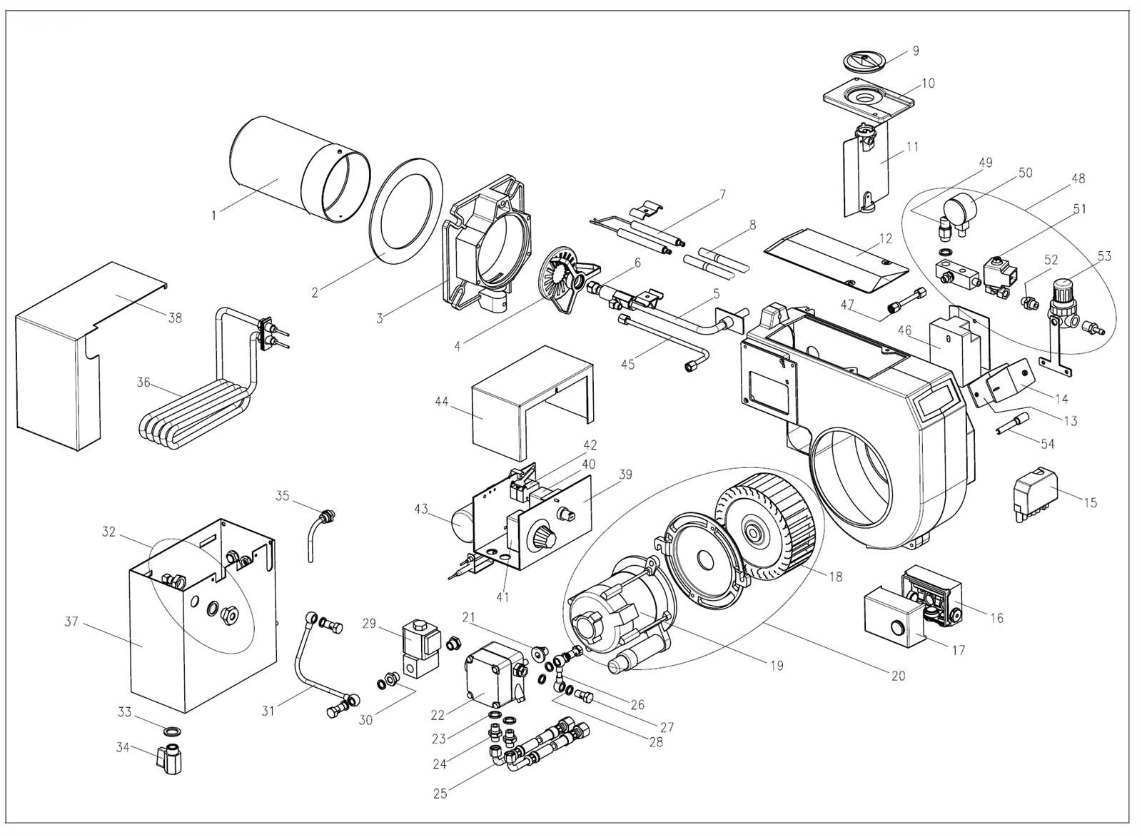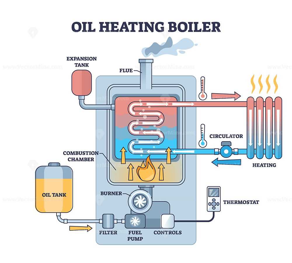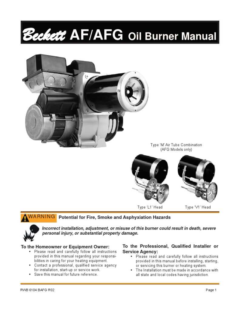
Efficient operation of heating systems relies on a clear understanding of their core components. Each element plays a crucial role in ensuring that the system functions smoothly and reliably over time. Whether you’re a technician or a homeowner, familiarizing yourself with these components is essential for proper maintenance and troubleshooting.
The complexity of these systems can sometimes be overwhelming, especially when trying to diagnose issues or replace faulty components. A detailed guide to the various components involved can provide valuable insights, making it easier to identify problems and understand how everything works together to produce heat.
By learning the essential elements, you’ll be better equipped to care for your equipment and avoid common issues. Understanding the purpose and function of each part allows for more informed decisions regarding repairs and replacements, ultimately improving the efficiency and longevity of your heating system.
Key Components of an Oil Burner
Every heating system relies on several interconnected components that ensure it operates efficiently. Each element contributes to the overall functionality, from fuel intake to combustion. Understanding these key components is crucial for troubleshooting, repairs, and maintaining optimal performance.
Fuel Delivery System
The first critical step in the process is delivering fuel to the combustion chamber. A properly functioning fuel delivery system ensures consistent and precise flow of fuel. The major components include:
- Fuel Pump: Draws fuel from the storage tank and pushes it toward the combustion chamber.
- Fuel Filter: Removes impurities from the fuel to prevent clogging and ensure smooth operation.
- Fuel Line: Carries the fuel from the tank to the combustion unit, ensuring it reaches the ignition point efficiently.
Combustion Assembly

The combustion assembly is where the fuel is ignited and converted into heat. Its components must work in harmony to maintain a safe and effective burning process:
- Ignition Transformer: Creates a high-voltage spark to ignite the fuel-air mixture inside the chamber.
- Electrode: Positioned near the nozzle to create a spark that ignites the fuel when it enters the combustion chamber.
- Flame Sensor: Detects the presence of a flame and ensures the system operates safely, shutting down if no flame is detected.
Understanding the Heating System Assembly
A heating system’s assembly is a carefully coordinated set of components that work together to generate heat efficiently. Each element plays a vital role in the smooth operation of the system, ensuring that the entire process–from fuel intake to heat production–occurs seamlessly. Knowing how these components interact is crucial for proper system maintenance and troubleshooting.
The assembly includes a combination of mechanical and electronic systems that control fuel flow, ignition, combustion, and exhaust. Understanding the relationship between these components helps ensure that the system functions as designed and can be repaired or replaced when necessary.
Among the most important aspects of the system assembly are the fuel delivery mechanism, combustion process, and the safety systems that monitor the entire operation. Recognizing how these parts work together makes it easier to identify potential issues before they cause significant disruptions.
Common Issues with Heating System Components
Like any complex system, heating equipment can encounter a range of issues over time. These problems often arise due to wear, improper maintenance, or faulty components. Identifying common failures early can help prevent costly repairs and downtime, ensuring that the system operates efficiently for as long as possible.
Fuel Delivery Problems
One of the most common issues is related to the delivery of fuel to the combustion chamber. A malfunction in this area can cause inconsistent heating or complete failure to ignite. Common problems include:
- Clogged Fuel Filter: A filter blocked by dirt or debris can restrict fuel flow, leading to weak or no ignition.
- Faulty Fuel Pump: A pump that fails to create enough pressure can result in inadequate fuel delivery, causing inefficient operation.
- Leaking Fuel Line: Fuel leaks from damaged lines can cause safety hazards and prevent proper fuel distribution.
Ignition and Combustion Failures

If the ignition system or combustion chamber malfunctions, it can prevent the system from generating heat. Some common issues include:
- Worn Ignition Electrodes: Electrodes that no longer produce a reliable spark can lead to ignition failure.
- Defective Flame Sensor: A sensor that fails to detect the flame can cause the system to shut down prematurely or fail to start.
- Dirty Nozzle: A clogged nozzle can prevent proper fuel atomization, leading to inefficient combustion and heat generation.