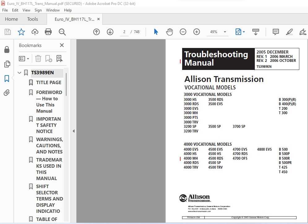
In the world of heavy-duty machinery, understanding the internal mechanisms of a complex gearbox system is crucial for effective maintenance and troubleshooting. Every system is composed of a variety of interrelated elements, each performing a specific function to ensure smooth operation. Proper knowledge of these components allows technicians and operators to diagnose issues quickly and avoid costly repairs.
Identifying the various components and their interactions is essential for anyone involved in the maintenance or repair of such systems. A clear visual guide can greatly simplify the process, providing a detailed breakdown of each part’s role. This guide will help users understand the structure and the specific functions of the individual elements that work together to power large vehicles and industrial machines.
Whether you’re a professional mechanic or an enthusiast, gaining a solid grasp of how each element functions within the whole system is key to keeping equipment in top condition. By mastering this knowledge, you’ll be able to extend the life of the machinery and ensure its optimal performance over time.
Understanding Heavy Duty Gearbox Components
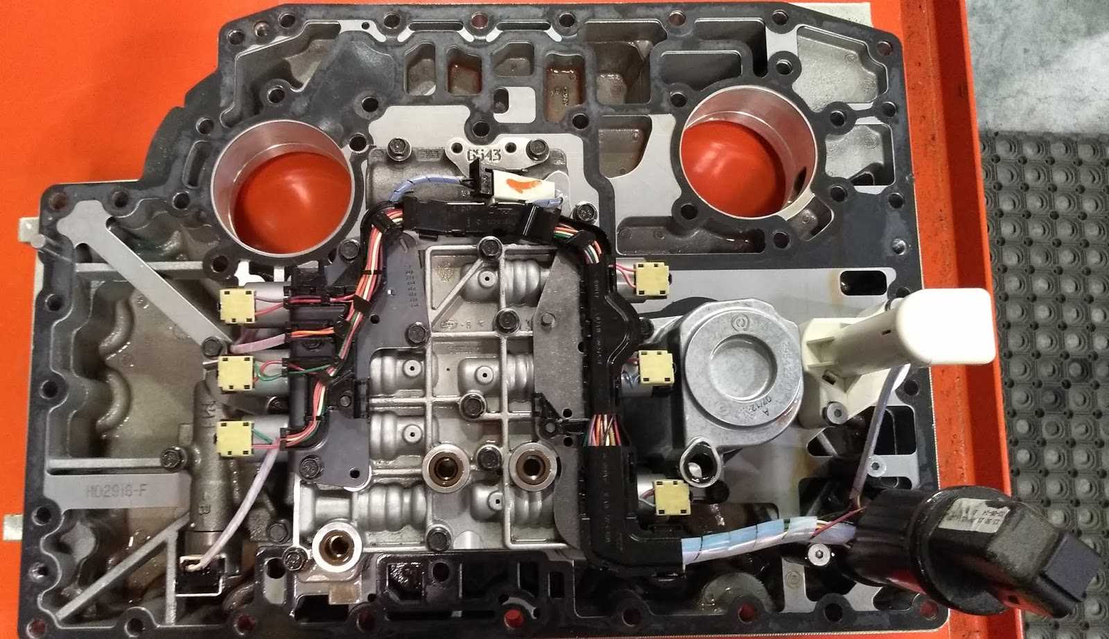
When working with complex machinery, it is essential to have a thorough understanding of the critical elements that make up the drivetrain system. Each component within the gearbox plays a vital role in ensuring smooth operation and efficient power transfer. By knowing how these elements work together, technicians can perform accurate diagnostics and effectively address issues as they arise.
The gearbox system in question consists of a variety of interdependent components, each designed to handle specific tasks such as regulating speed, torque, and direction of movement. These parts must function harmoniously to maintain optimal performance under various operating conditions. Understanding the individual characteristics of each element helps in troubleshooting and facilitates more efficient repairs and maintenance procedures.
Familiarity with these key components is not only beneficial for professionals but also for operators who wish to extend the longevity of their equipment. By mastering the essential functions of the parts within the system, users can ensure the machinery runs efficiently for an extended period while minimizing the risk of costly failures.
Key Components in the Heavy Duty Gearbox System
In any advanced drivetrain system, several crucial elements work together to ensure smooth operation and efficient performance. These key components are designed to manage the distribution of power, optimize efficiency, and provide reliability over long periods of use. Understanding their functions and interactions is essential for anyone looking to maintain or repair these complex systems.
Among the most important elements are the clutches, which engage and disengage various gears, allowing for smooth transitions between different power settings. The gears themselves play a critical role in adjusting speed and torque, ensuring the vehicle or machine operates at the right power level for different conditions. Another vital component is the valve body, which controls fluid flow and ensures that pressure is maintained at the appropriate levels for proper functioning.
The pump is responsible for supplying hydraulic pressure, which is necessary for operating the system. Additionally, the torque converter helps in transferring power smoothly from the engine to the drivetrain, allowing for efficient power use. Together, these components form the backbone of the system, each playing a unique role in ensuring the system’s overall performance and reliability.
How to Read the Parts Diagram
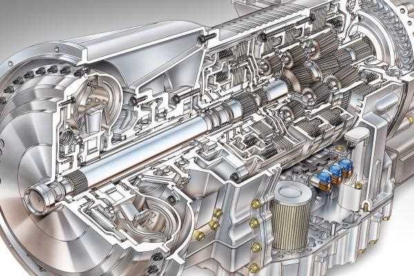
Understanding technical illustrations is essential for anyone involved in machinery maintenance or repair. These visual aids provide a detailed overview of the system’s layout, showing how the individual components fit and work together. Knowing how to interpret these images can significantly enhance your ability to diagnose problems and make accurate repairs.
Interpreting Symbols and Labels
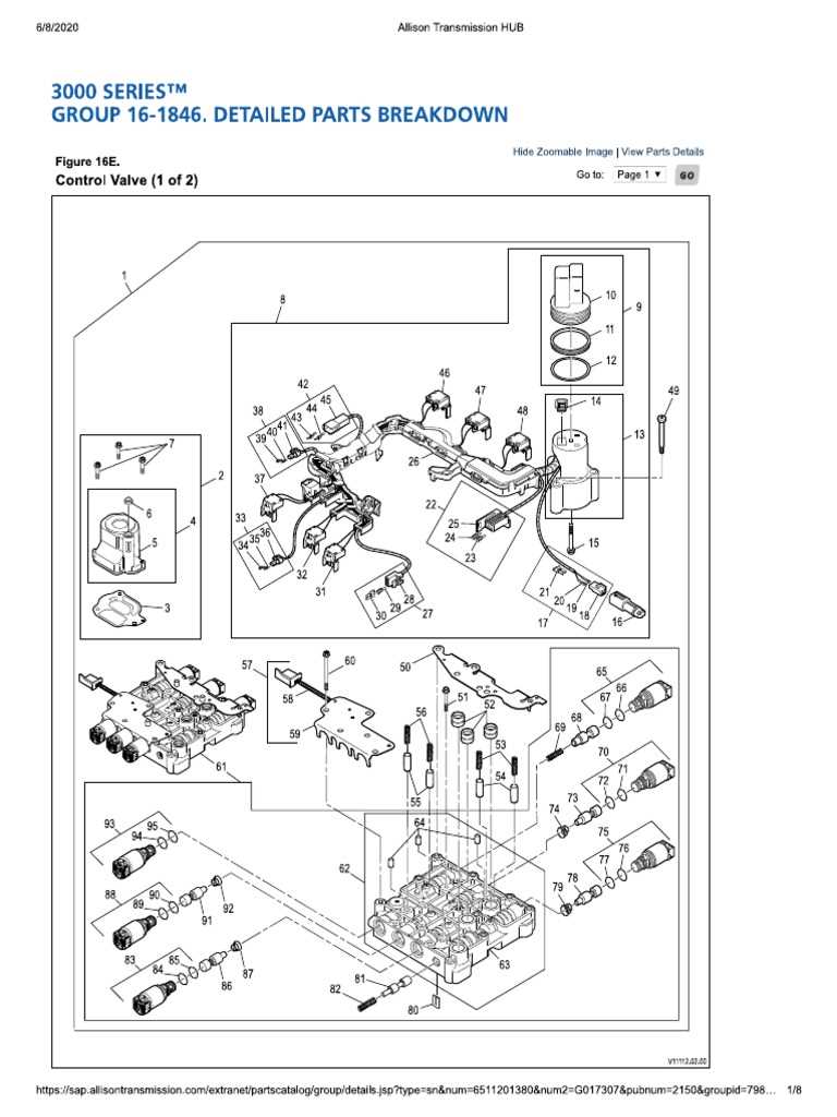
Each component in the illustration is represented by a specific symbol or label, which corresponds to a real-world part. These symbols are standardized to ensure consistency across different systems. Pay attention to any numbers or letters accompanying these symbols, as they often correspond to part numbers or designations that are critical when ordering replacements or referencing service manuals.
Understanding Relationships Between Components
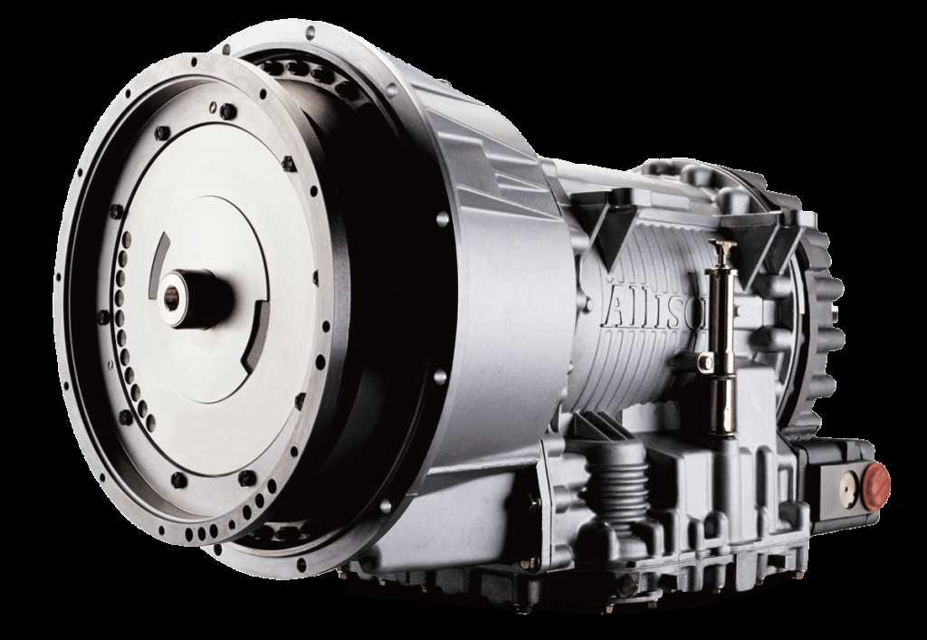
It is important to recognize how the parts interact with each other. Arrows and lines typically indicate the flow of fluid, energy, or mechanical movement between components. Understanding these connections helps clarify the operational flow and can assist in troubleshooting by identifying where issues may arise in the system.