When it comes to maintaining equipment, having a clear reference for identifying and replacing components is essential. This guide provides detailed insights into how to efficiently repair and maintain your tools and machines. By understanding the breakdown of various elements and their functions, users can ensure the longevity and proper functioning of their equipment.
How to Interpret Technical Schematics
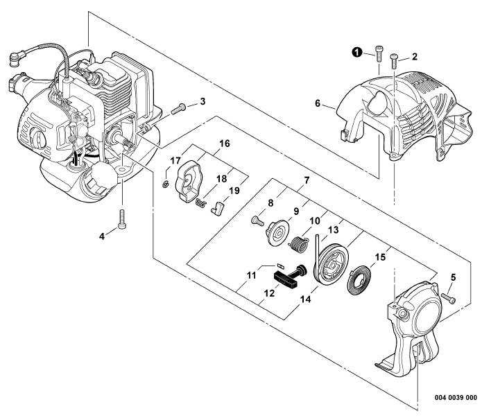
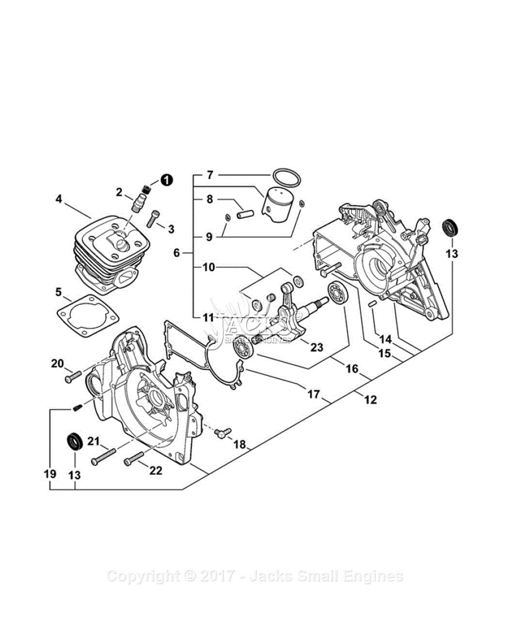
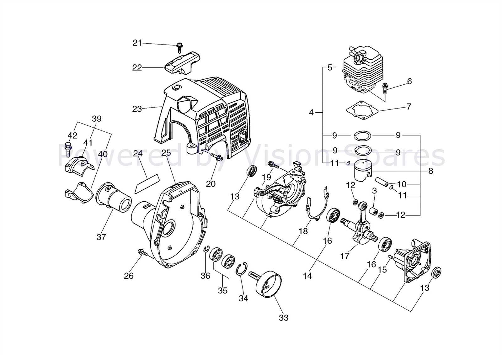
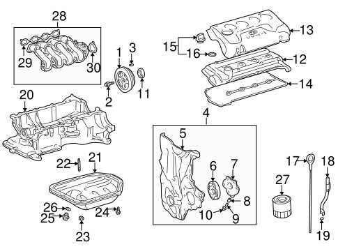
Reading and understanding repair manuals requires familiarity with technical layouts that depict the various parts of a machine. These guides usually feature numbered labels or codes that correspond to specific components. The more familiar you become with these representations, the easier it will be to pinpoint the part that needs attention.
Key Elements of a Repair Layout
- Visual Representation: Clear images that showcase the component arrangement.
- Labeling: Numbers or letters that correspond to parts listed in the manual.
- Part Identification: Information on what each item is, its function, and its location in the assembly.
Commonly Replaced Components
Over time, certain components of equipment experience wear and tear, requiring regular replacement. Knowing which parts are most prone to damage can help users prepare for repairs in advance. Some of the most frequently replaced items include:
- Filters: Vital for maintaining airflow and preventing damage to internal components.
- Belts: Often subject to friction and need replacing after extended use.
- Screws and Fasteners: Small but essential parts that keep the structure intact.
Tips for Easy Maintenance

Regular checks and proper storage conditions are key to preventing unnecessary damage. Always follow the manufacturer’s suggestions for upkeep to avoid malfunctions that could be easily prevented with routine care.
Understanding Equipment Layouts and Maintenance Guides

When it comes to maintaining machinery and tools, having a clear understanding of their internal structure is essential. A comprehensive visual reference helps identify crucial components, guiding users through the process of repair or replacement. Knowing how to interpret these illustrations can save both time and money by enabling efficient troubleshooting and part identification.
How to Read Technical Schematics
Technical schematics provide a detailed map of the various components within a machine. These layouts often include symbols, numbers, and labels that help users identify each part’s role and location. Understanding the relationship between different sections of the equipment allows for accurate identification of the faulty component and streamlines the repair process.
Common Elements and Their Functions

Every machine has a set of key components that work together to ensure smooth operation. These elements are often the ones that require the most attention during repairs. For example:
- Filters: Crucial for maintaining cleanliness and preventing damage from debris.
- Belts: Responsible for transferring power; they can wear out over time.
- Fasteners: Hold parts together and ensure structural integrity.
Recognizing these common parts helps prioritize maintenance tasks and prepares users for repairs ahead of time.
Accessing Schematics and Repair Information
Finding accurate visual guides is vital for proper repairs. Many resources are available online, from the manufacturer’s website to third-party platforms that host service manuals and user forums. These sources provide up-to-date and detailed schematics to ensure users have all the necessary information to complete the job successfully.