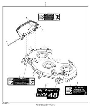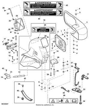
Maintaining your lawn equipment is crucial to ensuring its longevity and optimal performance. Knowing the various components and how they fit together can help you troubleshoot issues and carry out necessary repairs with confidence. This section aims to provide a comprehensive guide to understanding the key elements of your machine, making it easier to keep it in top condition.
Having access to a clear visual representation of all the individual parts is invaluable. It allows you to identify each piece, understand its function, and see how they interact within the entire system. With this knowledge, you can efficiently handle maintenance tasks or replace damaged parts without confusion or unnecessary delays.
Empowering yourself with a better understanding of the mechanical layout can significantly reduce repair costs and downtime. It also makes it easier to choose the right replacement components when needed, ensuring compatibility and optimal performance. The following guide will walk you through this process step by step.
Understanding the Lawn Equipment Mechanism
Maintaining and repairing lawn equipment requires a clear understanding of its underlying mechanism. The system is made up of several interconnected elements that work together to ensure efficient operation. Familiarity with these components not only aids in troubleshooting but also simplifies the process of carrying out maintenance tasks, whether it’s regular upkeep or addressing specific malfunctions.
At the heart of the machine lies the cutting assembly, which is responsible for delivering a clean, even cut across your lawn. This mechanism involves multiple moving parts that must be aligned correctly for the system to perform optimally. Additionally, components such as belts, pulleys, and springs play vital roles in controlling movement and providing the necessary tension to keep everything running smoothly.
Understanding how each part functions and how they fit into the overall design of the equipment can help you make informed decisions when performing repairs or upgrades. Whether you’re replacing worn-out components or upgrading to higher-quality materials, knowing how the various pieces interact is essential to maintaining the efficiency and longevity of your machine.
Key Components of the 48C Mower Deck

For optimal performance, it’s crucial to understand the essential components that contribute to the effective operation of your lawn equipment. Each element is designed to work seamlessly with others, ensuring that the system runs efficiently and delivers consistent results. Below are the key components that play an integral role in the smooth functioning of the entire mechanism.
Cutting Mechanism
The cutting system consists of sharp, durable blades that rotate at high speeds to achieve a precise and clean cut. These blades are typically powered by the engine and require proper alignment to function optimally. Regular maintenance, including sharpening or replacing the blades, ensures consistent cutting quality and reduces wear on other connected parts.
Drive Belts and Pulleys

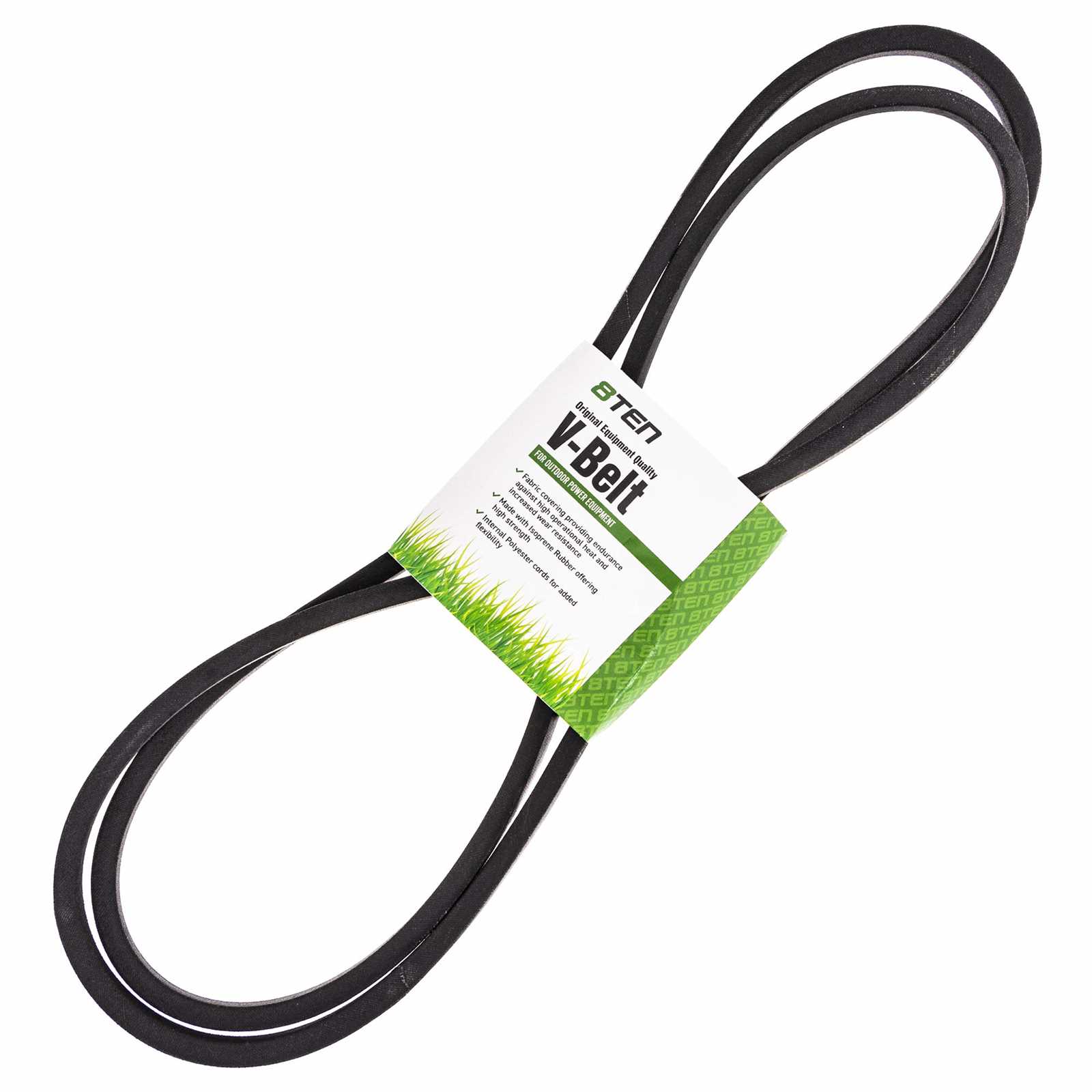
Drive belts and pulleys transfer power from the engine to various parts of the system, such as the cutting blades and other mechanical components. The tension on these belts must be maintained to prevent slippage or damage. Over time, wear and tear on the belts can cause them to lose efficiency, making it important to regularly inspect and replace them as necessary.
How to Read the Equipment Assembly Diagram
Understanding the layout of your equipment’s components can significantly simplify the maintenance and repair process. A visual representation of the machine’s structure helps identify the individual parts and their relationships with each other. Learning how to read these illustrations ensures that you can make informed decisions when performing repairs or replacements.
The key to interpreting an assembly diagram is focusing on the labeling system. Each component is usually numbered or marked with a specific code, which corresponds to a detailed list or reference guide. By cross-referencing these identifiers, you can quickly identify the part you need and understand its location within the larger assembly. This makes it easier to troubleshoot issues and ensure the correct part is ordered for replacement.