When it comes to maintaining and repairing a 35 HP marine engine, understanding its various elements is essential. Each component plays a crucial role in ensuring optimal performance and longevity. Whether you’re an experienced technician or a boat enthusiast, knowing how the different parts work together can save you time and effort during maintenance.
In this guide, we will explore the core components of a 35 HP motor, offering insights into their functions and interconnections. By familiarizing yourself with these key elements, you will be better equipped to identify potential issues and make informed decisions about repairs and replacements.
Learning how to identify each part and its placement within the engine can help you troubleshoot problems effectively. Understanding the structure will also give you confidence when performing routine checks or replacements to keep your engine running smoothly.
Understanding 35 HP Engine Components
Every marine engine consists of several key elements that work in harmony to deliver power and efficiency. For anyone looking to maintain or repair a 35 HP motor, understanding how these components interact is vital. From the ignition system to the propeller, each part has a specific function that supports the overall performance of the engine. In this section, we’ll break down the major components and their roles within the motor.
Core Engine Elements
The core components include the cylinder head, crankshaft, and pistons, which are responsible for creating the internal combustion that powers the motor. The cylinder head houses the valves, while the crankshaft transfers the power generated by the combustion to the rest of the system. The pistons move up and down, converting energy into mechanical work that propels the boat.
Supporting Systems
In addition to the main engine elements, several supporting systems contribute to the motor’s functionality. The fuel system, which includes the carburetor and fuel pump, ensures a steady supply of fuel to the engine. The cooling system, featuring a water pump and thermostat, regulates the engine’s temperature to prevent overheating. Additionally, the electrical system, including the battery and wiring, ensures that power is supplied to necessary components like the starter and ignition system.
By understanding how these key elements function individually and together, you can troubleshoot common issues and ensure the engine runs at its best for years to come.
Common Components of 35 HP Marine Engine

To keep a 35 HP marine engine running smoothly, it’s essential to recognize the main components that contribute to its performance. These elements are designed to work together seamlessly, ensuring the engine operates efficiently in various conditions. Understanding their functions allows for proper maintenance and troubleshooting when issues arise.
Among the most important parts are the fuel system, ignition system, and propulsion system. The fuel system includes the fuel pump and carburetor, which regulate the engine’s fuel supply. The ignition system, consisting of the spark plugs and coils, ensures proper firing and ignition timing. Meanwhile, the propulsion system, including the propeller and drive shaft, is responsible for converting engine power into motion that propels the boat forward.
Regular inspection of these common components will help prevent common failures and extend the life of the engine. Proper care of the fuel, ignition, and propulsion systems ensures reliable performance during boating adventures.
How to Read 35 HP Motor Schematic

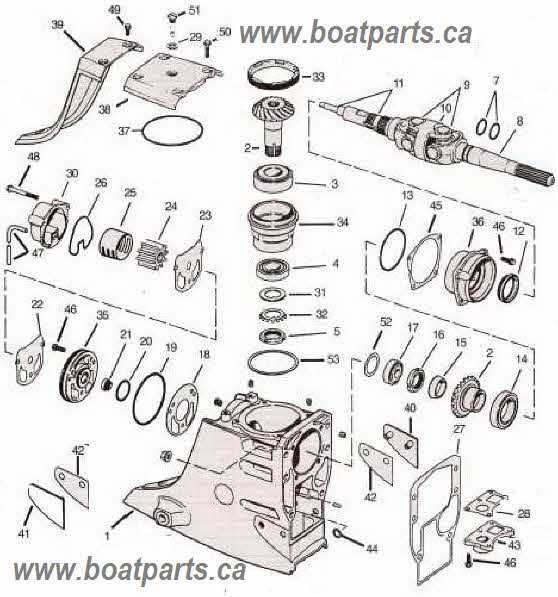
Understanding how to interpret a motor schematic is an essential skill for anyone working on a 35 HP engine. These diagrams provide a visual representation of the engine’s internal layout, making it easier to locate and identify specific components. By learning how to read these schematics, you can quickly diagnose issues, perform maintenance tasks, and assemble parts with confidence.
Identifying Key Components
At first glance, schematics may appear complex, but they typically use standardized symbols to represent different components. The engine’s major systems, such as the ignition, fuel, and cooling systems, are clearly labeled, making it easy to trace the flow of energy or fluid. Familiarizing yourself with these symbols will help you navigate the schematic and pinpoint specific areas of interest when troubleshooting or servicing the engine.
Understanding Connections and Flow
One of the most important aspects of reading a schematic is understanding how different parts are connected. Arrows and lines indicate how electrical currents, fuel, and coolant move through the motor. By following these lines, you can determine how the engine functions as a whole and identify potential issues, such as blocked pathways or damaged connections.
With practice, reading and interpreting schematics will become a valuable tool in your ability to maintain and repair the engine efficiently.