When it comes to maintaining outdoor power equipment, understanding how each component fits together is crucial for effective repair and upkeep. A clear illustration of all components can help you identify worn-out or damaged parts quickly, saving both time and money in the long run.
Properly understanding the structure and functioning of your tool ensures that you can perform necessary repairs with ease. Knowing the individual elements also aids in selecting the correct replacements, ensuring a seamless repair process and optimal performance.
Whether you’re replacing a part for the first time or performing regular maintenance, familiarizing yourself with the key components can extend the life of your equipment. In this guide, we will explore how to read detailed illustrations of the equipment’s inner workings and pinpoint common issues requiring attention.
Understanding the Stihl FS 56 RC Parts

To ensure that your equipment functions optimally, it’s essential to have a clear understanding of its internal structure. Each component works together to provide smooth operation, and recognizing how these parts interact allows for better maintenance and troubleshooting.
Key Components of the Tool
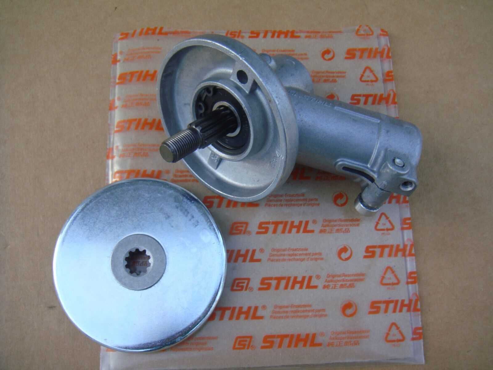
Familiarity with the primary components can make it easier to spot issues. The engine, drive shaft, and cutting head are among the most crucial elements. These parts are responsible for powering and controlling the overall performance of the device, making their condition vital for efficient operation.
How Each Component Contributes to Performance
Each part contributes to the machine’s performance in a specific way. For example, the engine provides the power needed to operate the tool, while the cutting head is designed to manage the workload during use. Understanding how these elements work together ensures better care and longevity of the equipment.
How to Read the Parts Diagram
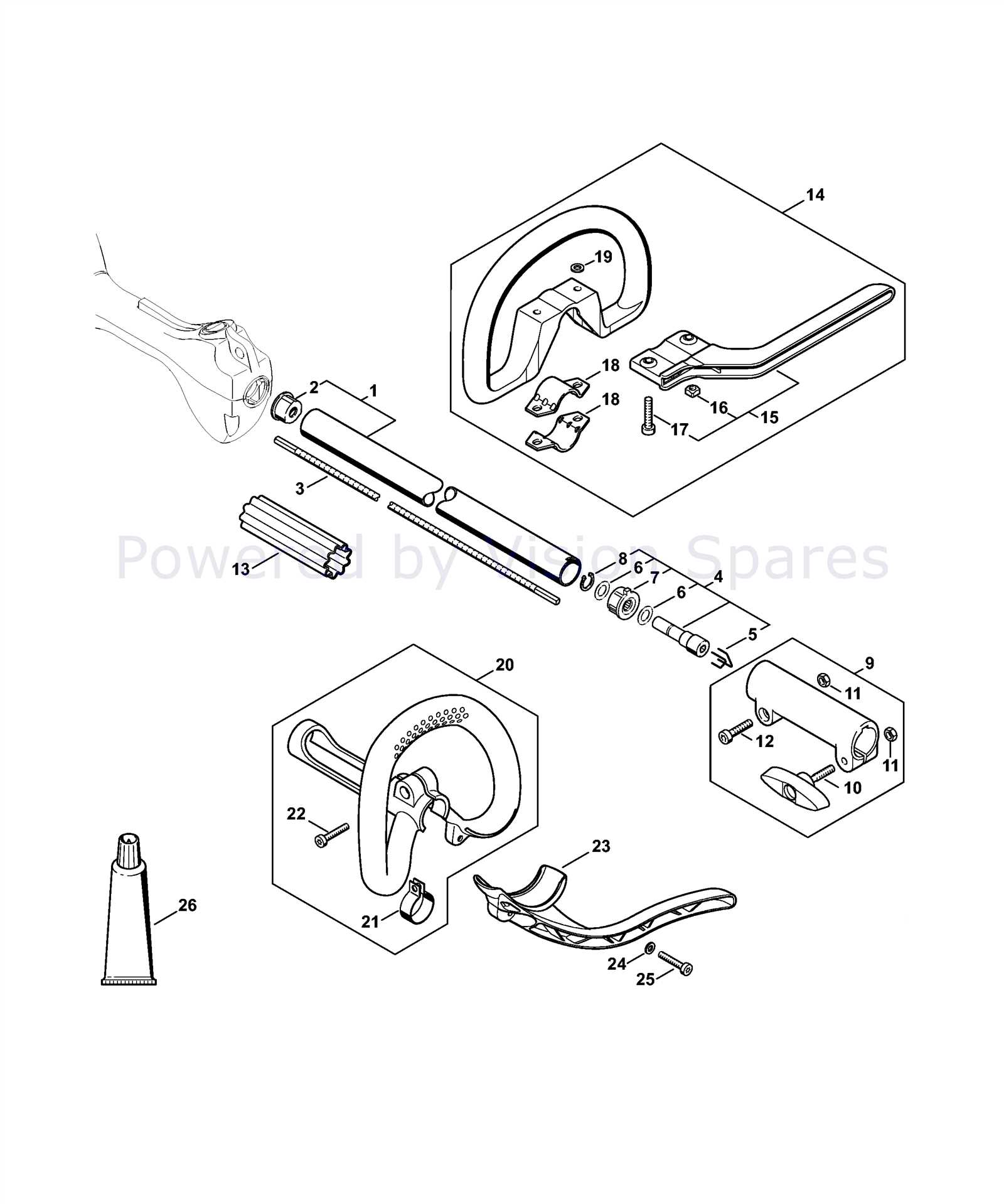
Interpreting the visual representation of your equipment’s components can significantly aid in identifying and replacing individual parts. By understanding how each part is labeled and connected, you can easily locate any worn or damaged pieces that need attention.
Decoding the Visual Key

Every diagram uses a visual system that helps break down the structure of the tool. The key to reading these diagrams is recognizing the numbers and labels that correspond to specific components. Typically, each part is shown in its exact position and is numbered for easy reference.
- Numbers and labels help identify each individual component.
- Color coding may be used to distinguish different sections or systems.
- Lines connecting parts show how each element is linked together.
Following the Assembly Order

Understanding the order in which parts are assembled is crucial when replacing or repairing your tool. By following the steps shown in the diagram, you can ensure proper reassembly of the components, avoiding mistakes that might affect performance.
- Start with the base components that are attached first.
- Move on to smaller parts that fit within the larger framework.
- Check for proper alignment before securing everything in place.
Common Replacements for the FS 56 RC
Over time, certain components of your equipment may experience wear and tear, requiring replacement to maintain optimal performance. Knowing which parts commonly need replacing helps ensure the tool continues to function efficiently and reliably.
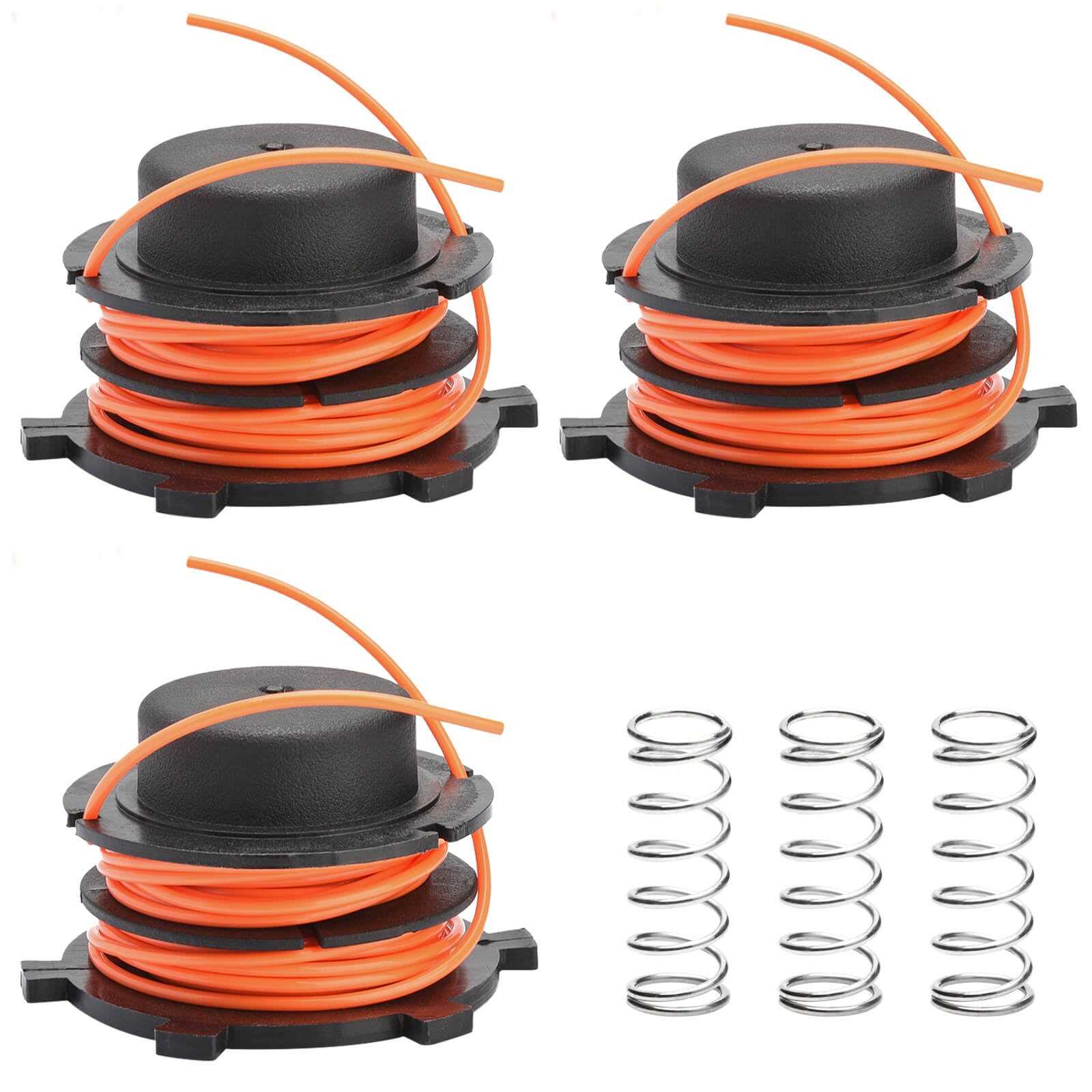
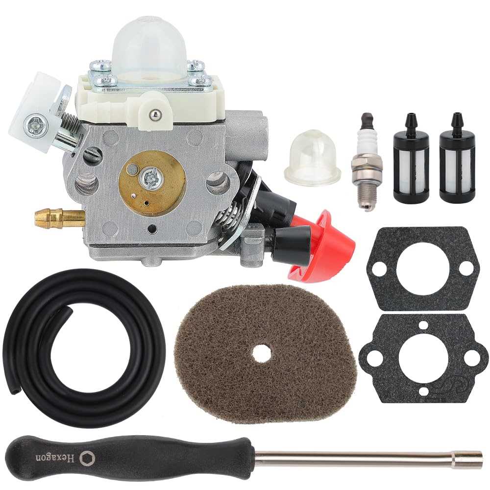
Commonly replaced elements include the cutting head, fuel lines, and spark plug. These components are crucial for the tool’s operation, and frequent use can lead to degradation, affecting performance. Regular checks and timely replacements help keep your equipment running smoothly.
Another common replacement is the air filter. As it gets clogged with debris, it can reduce engine efficiency. Replacing it ensures proper airflow and fuel combustion, extending the life of your tool. Similarly, the throttle cable may need to be replaced if it becomes frayed or stiff, affecting control over the engine speed.