Electric running boards are a valuable addition to modern vehicles, offering both convenience and enhanced functionality. These systems are designed to automatically extend and retract, providing easier access to the vehicle. Understanding their inner workings can help you maintain and repair them effectively when necessary.
In this guide, we will explore the key elements that make up these automated boards. By breaking down the system’s different components, you can gain a better understanding of how they function together. This knowledge is crucial for anyone looking to perform maintenance, troubleshoot, or replace parts.
Knowing how to interpret these intricate systems can save time and prevent unnecessary repairs. Whether you are a vehicle owner or a technician, being familiar with the design and operation of these features is essential for optimal performance.
Understanding Electric Running Board Systems
Electric running boards are a sophisticated feature designed to improve vehicle accessibility and functionality. These systems automatically deploy when the door is opened, offering a convenient step to help passengers enter and exit the vehicle with ease. They retract when not in use, maintaining a sleek profile while driving.
The mechanism behind these running boards relies on various components that work in unison. These elements are carefully engineered to ensure smooth and reliable operation, even under tough conditions. Understanding how each part contributes to the overall system is essential for anyone looking to troubleshoot, maintain, or replace components effectively.
When properly maintained, these systems enhance both the aesthetics and practicality of your vehicle, making them a worthwhile investment. Knowing how the individual components interact ensures that the running boards will perform optimally for years to come.
Essential Components of Power Step Systems
The automatic running board system relies on several crucial elements that work together to ensure smooth operation. Each part serves a specific purpose, allowing the system to extend when needed and retract seamlessly when not in use. Familiarizing yourself with these components is vital for understanding how the system functions and maintaining its performance.
Motor and Actuator

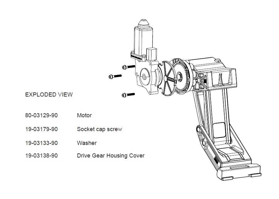
The motor and actuator are the heart of the system, providing the necessary movement for the boards to extend and retract. The motor is typically activated when the vehicle door is opened, initiating the deployment process. The actuator converts the motor’s power into mechanical motion, moving the board into place and ensuring it stays securely extended until the door is closed.
Control Module
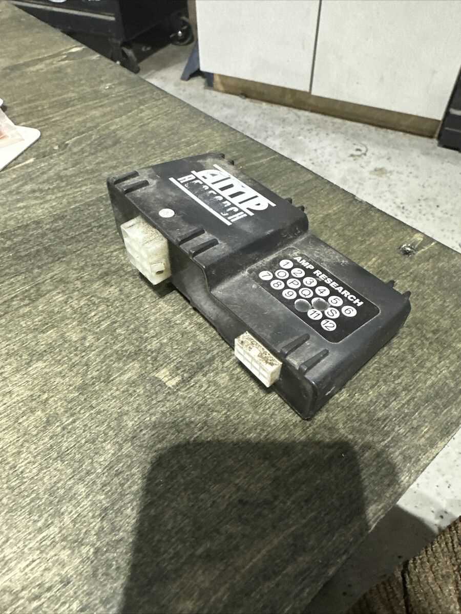
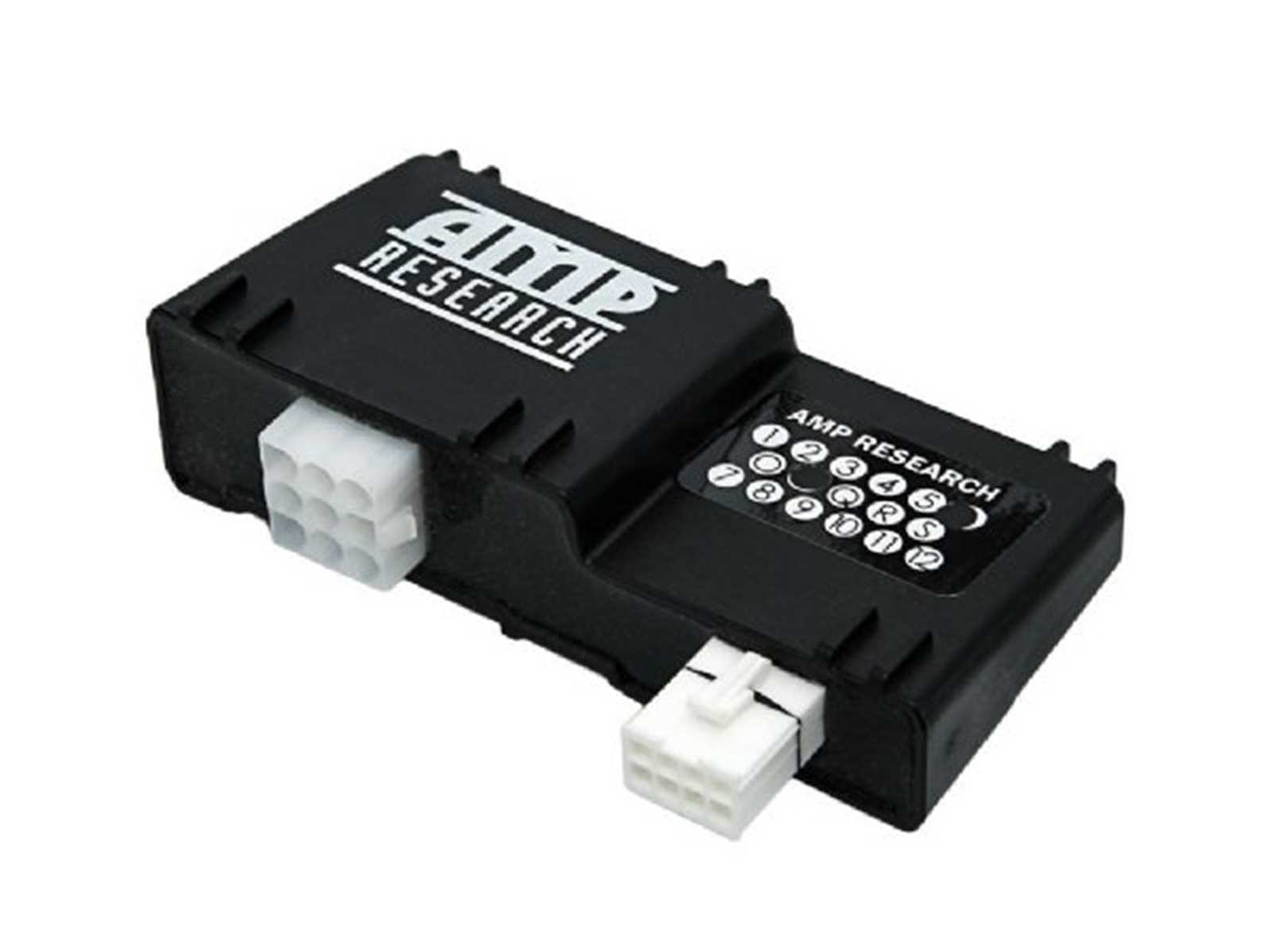
The control module is the brain of the system, responsible for managing the interaction between the motor, actuator, and other components. It receives signals from the vehicle’s door sensors and determines when to activate the system. The control module also monitors the system for faults and ensures it operates within the correct parameters.
How to Read the Power Step Diagram

Understanding the layout and components of an automatic running board system can be crucial for troubleshooting and repairs. A visual representation of these elements helps identify each part and its function within the overall mechanism. By interpreting the diagram correctly, you can pinpoint any issues and determine which components need attention.
The diagram typically includes detailed illustrations of the components, along with labels and descriptions that outline their specific roles. Pay close attention to the connections between parts, as they often reveal how the system operates as a whole. It’s also important to recognize the flow of power and control signals, as this will help you understand how the system is activated and managed.
Familiarizing yourself with the symbols and annotations used in the diagram will allow you to navigate the document efficiently. Once you can identify key elements like the motor, actuator, and control module, reading and interpreting the diagram becomes much easier. This knowledge is essential for anyone working on the system to ensure proper maintenance and repair.