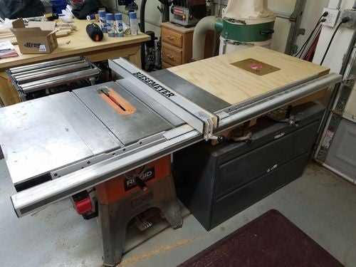
When maintaining or repairing any power tool, understanding the layout of its components is essential for effective troubleshooting. Having a clear overview of how each part fits together can save time and effort, allowing you to address issues promptly. Whether you’re replacing a worn-out element or conducting routine maintenance, knowing where each piece belongs is crucial for a successful repair.
Proper knowledge of tool parts ensures that you can identify what needs replacement or adjustment. With the right visual references and descriptions, even complex machines become manageable. By familiarizing yourself with the internal structure, you can confidently navigate repairs and avoid unnecessary confusion during disassembly or reassembly.
In this guide, we will explore the key components of your tool, providing a detailed visual aid that will assist in identifying each part. Whether you’re a seasoned professional or a DIY enthusiast, this resource will simplify the repair process and help you maintain your equipment in top condition.
Understanding Tool Component Layout
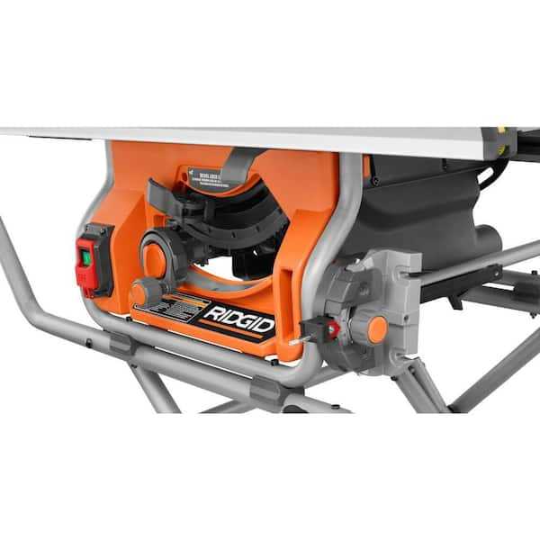
When dealing with complex machinery, having a clear map of the internal configuration is essential for proper maintenance. Each tool is composed of various interconnected elements, each serving a specific function. Recognizing the role of every piece and how it interacts with others is vital for efficient repairs and upkeep. A well-detailed layout helps you identify the parts that need attention and ensures that replacements or adjustments are made correctly.
Key Elements and Their Functions
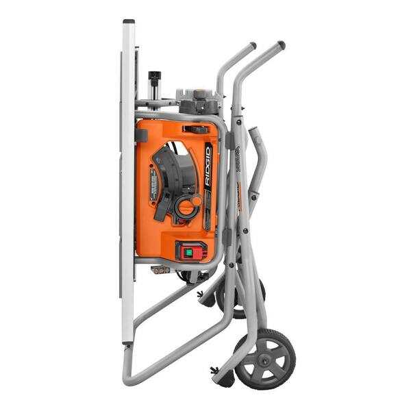
Every tool is designed with essential components that work together to perform specific tasks. From motors to safety mechanisms, understanding what each element does within the system allows you to quickly diagnose issues. For example, the drive mechanism controls power delivery, while safety guards and switches ensure user protection. By breaking down the layout into manageable sections, you can tackle repairs methodically.
How to Use a Component Layout for Repairs
Once you have a clear understanding of the layout, you can begin using it as a roadmap for repairs. Identifying damaged or worn-out components becomes easier, and you can quickly determine the necessary replacements. The visual guide acts as a helpful tool for assembling or disassembling machinery, ensuring that no part is overlooked. By following the correct sequence, you avoid causing further damage during maintenance tasks.
How to Read the Component Layout
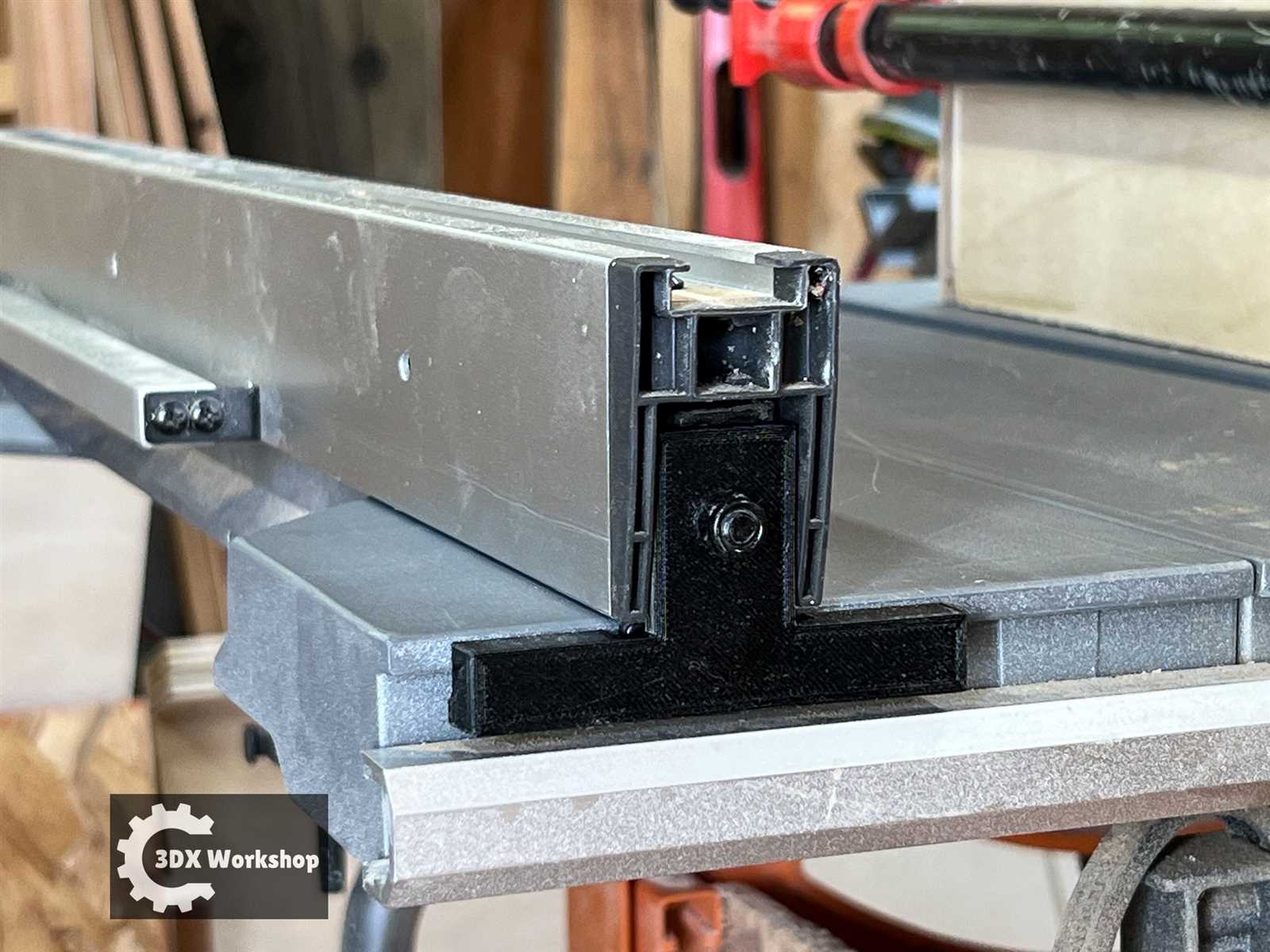
Understanding a machine’s internal blueprint is essential for effective maintenance and repair. A visual representation of the tool’s structure simplifies the process of identifying each element and its position within the assembly. By carefully examining this layout, you can quickly locate the parts that need attention, allowing for efficient and accurate repairs.
Identifying Key Symbols and Labels
Most layouts use specific symbols and labels to represent various components. These may include numbers, letters, or even color codes that correspond to different sections or functions of the tool. Familiarizing yourself with these markers is the first step in correctly interpreting the diagram. Once you know what each symbol signifies, identifying the relevant parts becomes straightforward.
Following the Assembly Sequence
One of the most important aspects of understanding the layout is recognizing the assembly order. The diagram usually illustrates the tool’s construction step-by-step, showing how each component fits into place. By following the sequence carefully, you can ensure that the disassembly and reassembly processes go smoothly, minimizing the risk of errors or damage during repairs.
Common Components for Tool Repair
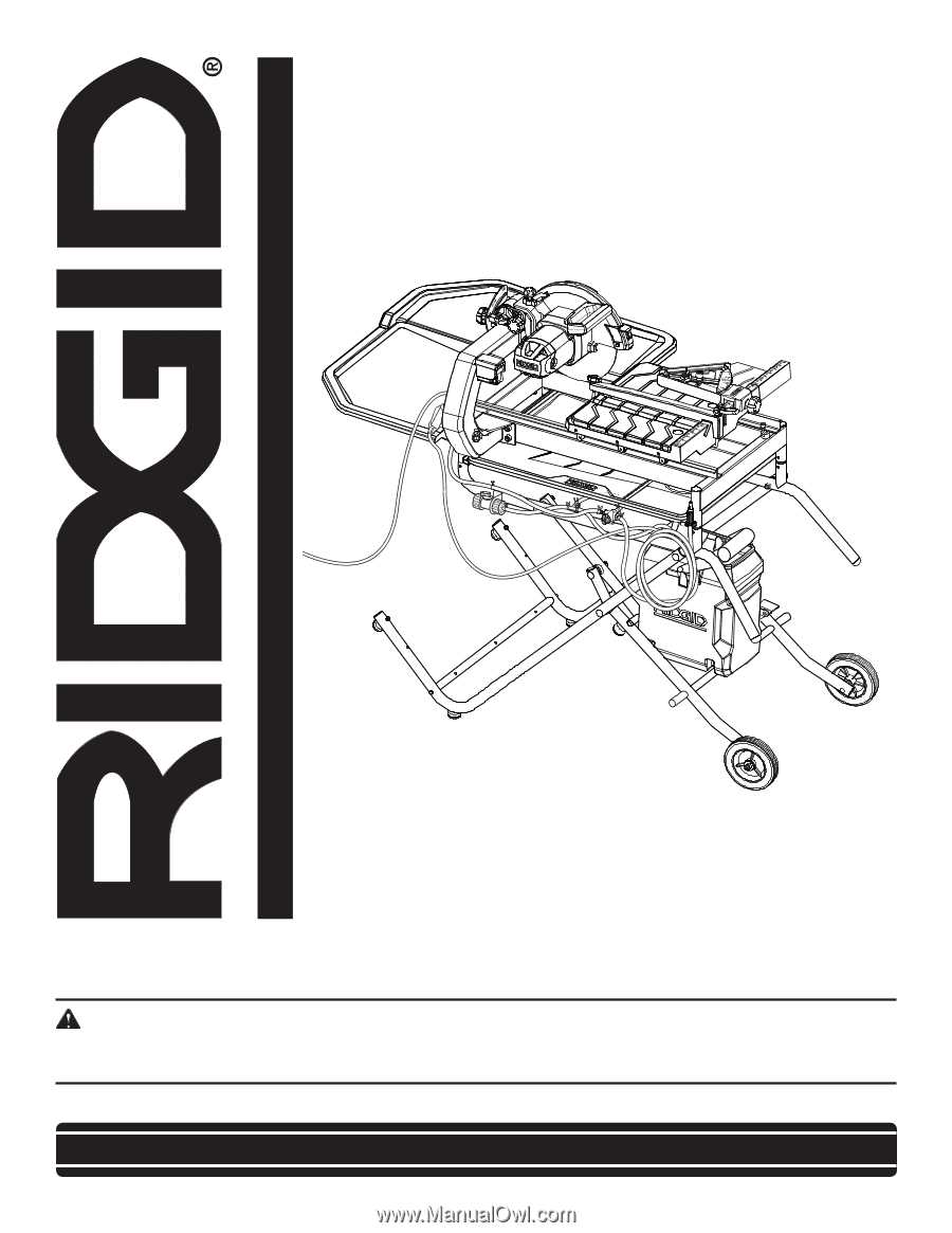
When it comes to fixing a machine, there are several key components that are frequently replaced or serviced. These parts play critical roles in the overall functionality, and ensuring they are in good condition is essential for the tool’s performance. Knowing which parts are most commonly affected can help you prioritize repairs and avoid unnecessary downtime.
Motor and Drive Mechanisms
The motor is one of the most vital elements in any tool, and issues with it can lead to a complete malfunction. Over time, wear and tear can cause motor failure, or the drive system may become misaligned or damaged. Regular checks and timely replacement of these components are essential to keep the tool running smoothly and avoid more costly repairs in the future.
Switches and Safety Features
Switches and safety mechanisms are integral for both performance and user protection. A malfunctioning switch can prevent the tool from turning on, while damaged safety features can lead to hazardous operating conditions. Replacing faulty switches and ensuring safety features are functioning properly will extend the life of the tool and ensure safe operation during use.