Understanding the internal structure of your vehicle or machine is crucial for effective maintenance and repair. Every model comes with a detailed map of its essential elements, allowing owners to identify and address any issues with precision. Knowing how each part functions and interacts is key to preserving the longevity and performance of your equipment.
In this article, we’ll explore how to interpret the layout of different components, making it easier to pinpoint problems and perform necessary repairs. With clear visual aids and explanations, you’ll gain the confidence to handle even complex tasks. Whether you’re a professional technician or a DIY enthusiast, having a clear understanding of your machine’s structure is indispensable.
By learning how to read and use these visual guides effectively, you can save time and money on repairs while ensuring that your equipment operates smoothly for years to come. The process will also help you become more familiar with the critical components of your vehicle or machine, empowering you to maintain it properly.
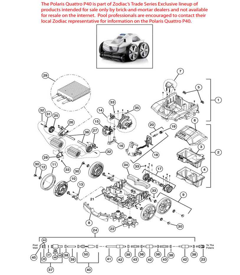
Understanding the Polaris 180 Parts Diagram
To maintain and repair any mechanical system efficiently, it is essential to have a clear understanding of its layout. Visual guides depicting the intricate arrangement of parts provide a comprehensive map, allowing users to identify each element quickly. These tools simplify the repair process by showing the exact location and function of each component, which helps in troubleshooting issues effectively.
How Visual Guides Enhance Repair Accuracy
These guides help by breaking down complex structures into easily recognizable sections, making it easier to locate specific elements within a system. They provide a clear reference point for technicians, allowing them to focus on the problem areas with minimal confusion. With proper knowledge of how these parts are interconnected, repairs become faster and more precise.
Key Features to Identify in the Visual Layout
In the layout, you’ll find components labeled according to their function and position, such as the power unit, control systems, and structural parts. Understanding the relationship between these elements enables you to assess wear and tear and address specific issues more effectively. It’s crucial to identify key features such as connectors, fasteners, and moving parts, as they often require special attention during repairs or replacements.
How to Identify Key Components of the Polaris 180
Knowing how to pinpoint the critical elements within a machine or vehicle is vital for effective maintenance and repair. Each component serves a specific role, and identifying them ensures that you can address issues without causing further damage. This section will help you understand the core parts that require attention and how to identify them accurately within the visual guide.
Locating the Main Functional Units

The primary sections to focus on are the power unit, transmission, and control mechanisms. These units are central to the operation of the system, and understanding their function allows you to troubleshoot effectively. By studying the layout, you’ll be able to distinguish these units based on their placement and interaction with other components. The power unit, for example, is often the largest and most complex section, while the transmission may be grouped with similar elements for easier identification.
Identifying Smaller Critical Parts
In addition to the main components, smaller yet equally important parts such as connectors, seals, and fasteners must be identified. These parts are often prone to wear and can lead to performance issues if not properly maintained. Pay attention to the placement and type of each piece, as knowing where each part fits can save significant time during repairs. Using the guide effectively ensures you won’t overlook these smaller, but crucial, elements.
Step-by-Step Guide to Using the Diagram for Repairs

Effective repairs begin with a clear understanding of the system layout. By using the visual guide to locate and identify each component, you can approach the repair process methodically and reduce the risk of errors. This guide will walk you through the essential steps, helping you leverage the layout to perform repairs quickly and accurately.
Step 1: Examine the Entire Layout
Before starting any repair, take a moment to familiarize yourself with the entire system. Study the layout to get a sense of where each key component is positioned. This will give you a visual reference point and help you avoid confusion when locating specific parts. Having a clear overview of the structure will allow you to approach the repair systematically, ensuring that no part is overlooked.
Step 2: Identify Problem Areas
Once you understand the general layout, focus on identifying areas that require attention. Look for components that show signs of wear, damage, or malfunction. The guide will highlight these parts, helping you determine exactly where to focus your efforts. Pay special attention to the condition of connectors, seals, and other small components, as these are often the source of issues.