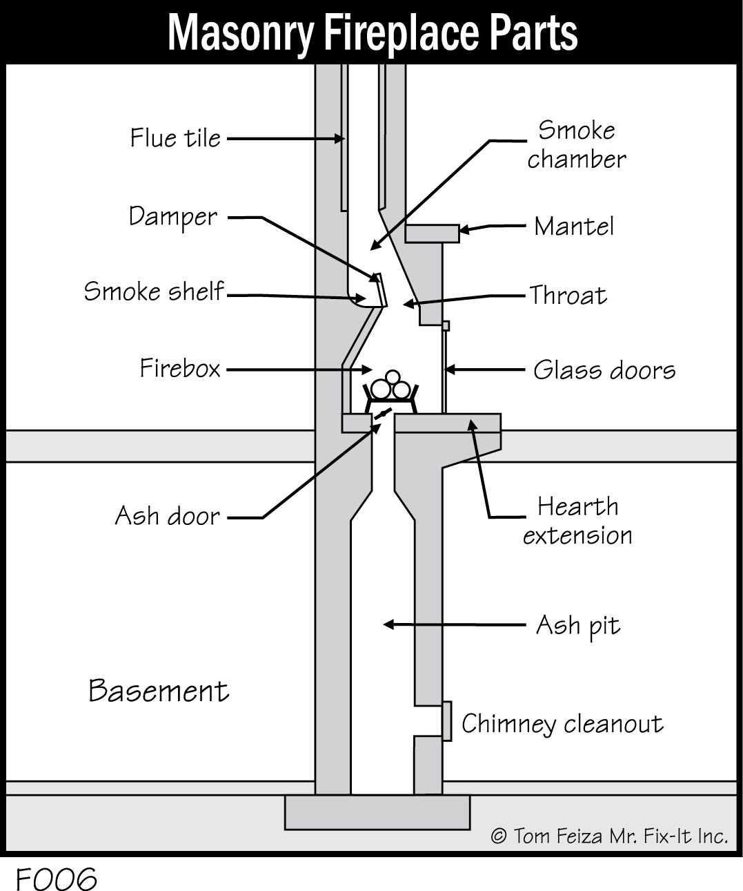
Every functional structure designed for ventilation involves specific components that work together to ensure proper airflow and safety. These elements are crucial for maintaining efficiency and preventing potential hazards. A clear understanding of their roles and interconnections is essential for both installation and maintenance.
Each element plays a distinct role, whether it’s guiding air out of a building or protecting the structure from heat and corrosion. The system is designed to withstand extreme conditions while ensuring maximum performance. By examining how these components interact, one can better appreciate their importance in the overall functionality.
In this section, we will explore the essential components involved, providing a detailed overview of their structure and purpose. Through a clearer understanding, proper maintenance and troubleshooting can be more effectively carried out, ensuring the longevity of the entire system.
Key Components of a Ventilation System
To ensure a safe and effective airflow from inside to outside a building, the system relies on several crucial elements. These components are designed to work in harmony, enabling efficient operation and minimizing risks associated with heat, smoke, or harmful gases. Understanding each part’s function is vital for proper installation and regular maintenance.
Main Structure for Airflow
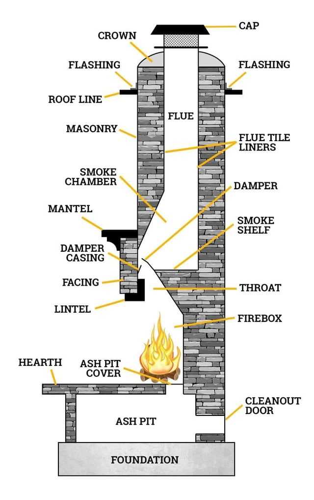
The main structure is responsible for guiding gases and heat away from the interior. This section needs to be robust and durable, capable of withstanding high temperatures while preventing heat loss. The material used for this part must also be resistant to environmental factors, ensuring longevity and safety.
Protective Elements and Accessories
In addition to the main framework, protective elements play an essential role in safeguarding the system. These include mechanisms that prevent debris from entering or ensure that the structure is sealed tightly to avoid leaks. Accessories like caps and liners contribute to the overall safety by enhancing the durability of the entire setup.
How a Venting System Functions and its Components
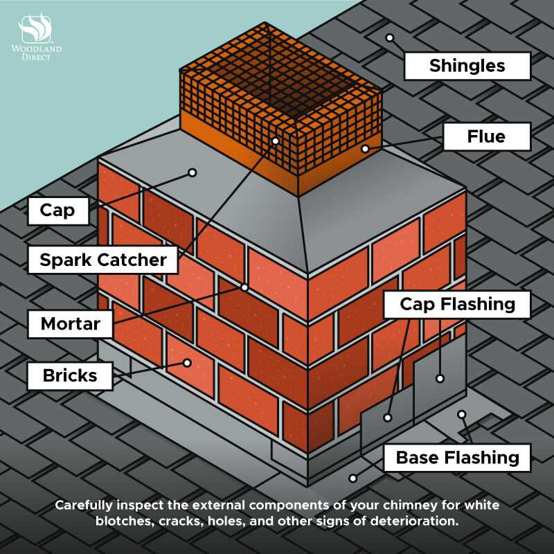
The function of a venting system is to direct gases, smoke, and heat away from the interior of a building, ensuring both safety and efficiency. For this process to work smoothly, it relies on several integrated components that serve distinct roles in the system. Each element must be designed to handle high temperatures and various environmental conditions to prevent damage or failure.
The flow of air is initiated from the inside, with heated air or smoke rising through the structure due to the natural upward force. This movement is crucial for expelling the harmful byproducts of combustion. A well-functioning system maintains consistent airflow to avoid backdrafts or blockages, ensuring that the building remains free from hazardous gases.
In addition to the primary components that direct airflow, supportive elements help regulate the system’s efficiency. These parts include seals, liners, and covers, which protect against corrosion, optimize performance, and provide a secure connection between each segment of the structure. Proper installation and maintenance of these components are essential for the system’s long-term functionality and safety.
Understanding Venting Structure with Diagrams
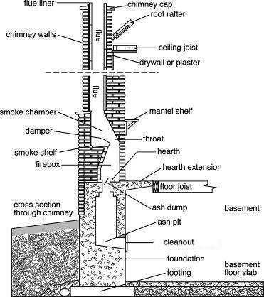
Visual representations play a crucial role in understanding the configuration of a venting system. By breaking down the structure into individual components, diagrams provide clarity on how each element fits together and functions. These visuals simplify the complexity of the system, highlighting its key sections and their interconnections.
Key Elements Shown in the Diagram
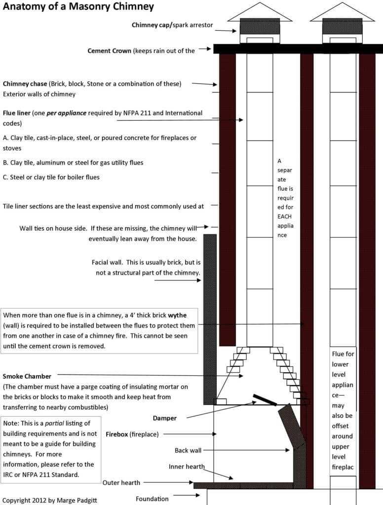
In a typical visual representation, the following components are often depicted:
- Main shaft – The central channel through which gases and smoke travel.
- Seals and liners – Protecting surfaces to maintain efficiency and prevent damage.
- Exhaust cap – Ensuring that air and gases are released safely into the atmosphere.
- Supporting brackets – Providing structural integrity and stability to the entire system.
Why Diagrams Are Useful
Diagrams are essential tools for both learning and troubleshooting. They allow users to see the system as a whole, making it easier to understand the flow of air and the roles each section plays. By clearly illustrating the connections between different elements, these visuals help in both installation and maintenance processes, ensuring everything is correctly positioned for optimal performance.