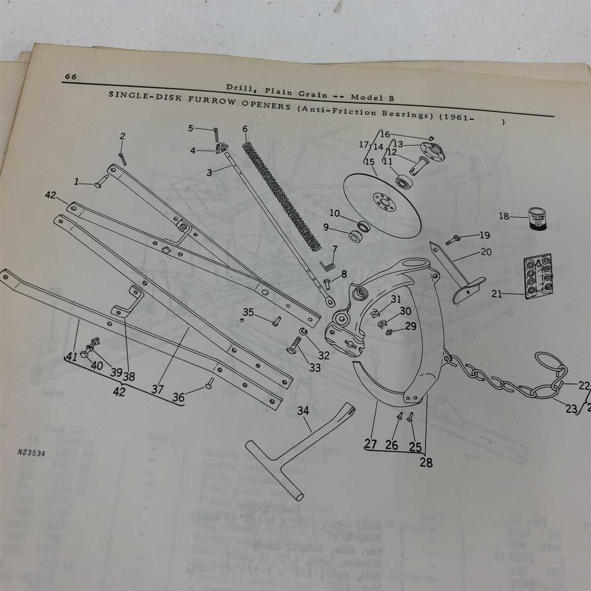
Understanding the intricate layout of agricultural machinery is essential for anyone involved in maintenance or repair. With the right knowledge of how different parts interact, keeping equipment in top condition becomes much easier. This section offers a closer look at a specific model, focusing on its structure and key elements.
Proper identification of each component allows for efficient troubleshooting and ensures that maintenance tasks are performed correctly. Whether you’re dealing with mechanical issues or simply performing routine checks, knowing the function of each piece is crucial.
From the engine to the wheels, each part plays a vital role in the overall performance. This guide will help you navigate through the layout, providing insights into how the different elements work together to ensure smooth operation of the machinery.
Understanding the John Deere B Parts Layout
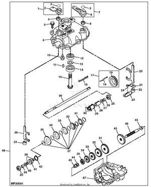
Every machine is a collection of interconnected elements, each serving a unique function to ensure smooth operation. Understanding the layout of these components is key to effective maintenance and repairs. In this section, we’ll explore how the different sections of the equipment work together, focusing on the most crucial aspects that keep it running at its best.
Essential Sections of the Machinery
The structure of this particular model consists of several main units that are designed to work in harmony. The engine, transmission, and chassis are some of the most vital elements that support the vehicle’s performance. Knowing the role of each part within these systems allows for better planning of repairs and maintenance.
Key Elements and Their Functions
Components like the engine block and transmission system play significant roles in the machinery’s operation. These parts provide power and control, making it possible for the equipment to perform tasks efficiently. Understanding how each piece fits into the bigger picture helps avoid unnecessary confusion during troubleshooting.
Maintenance and repair become more manageable when you have a clear understanding of how the different elements function together. This knowledge ensures that any issues can be addressed quickly and with precision, preventing downtime and extending the lifespan of the machine.
Key Components of the John Deere B Tractor
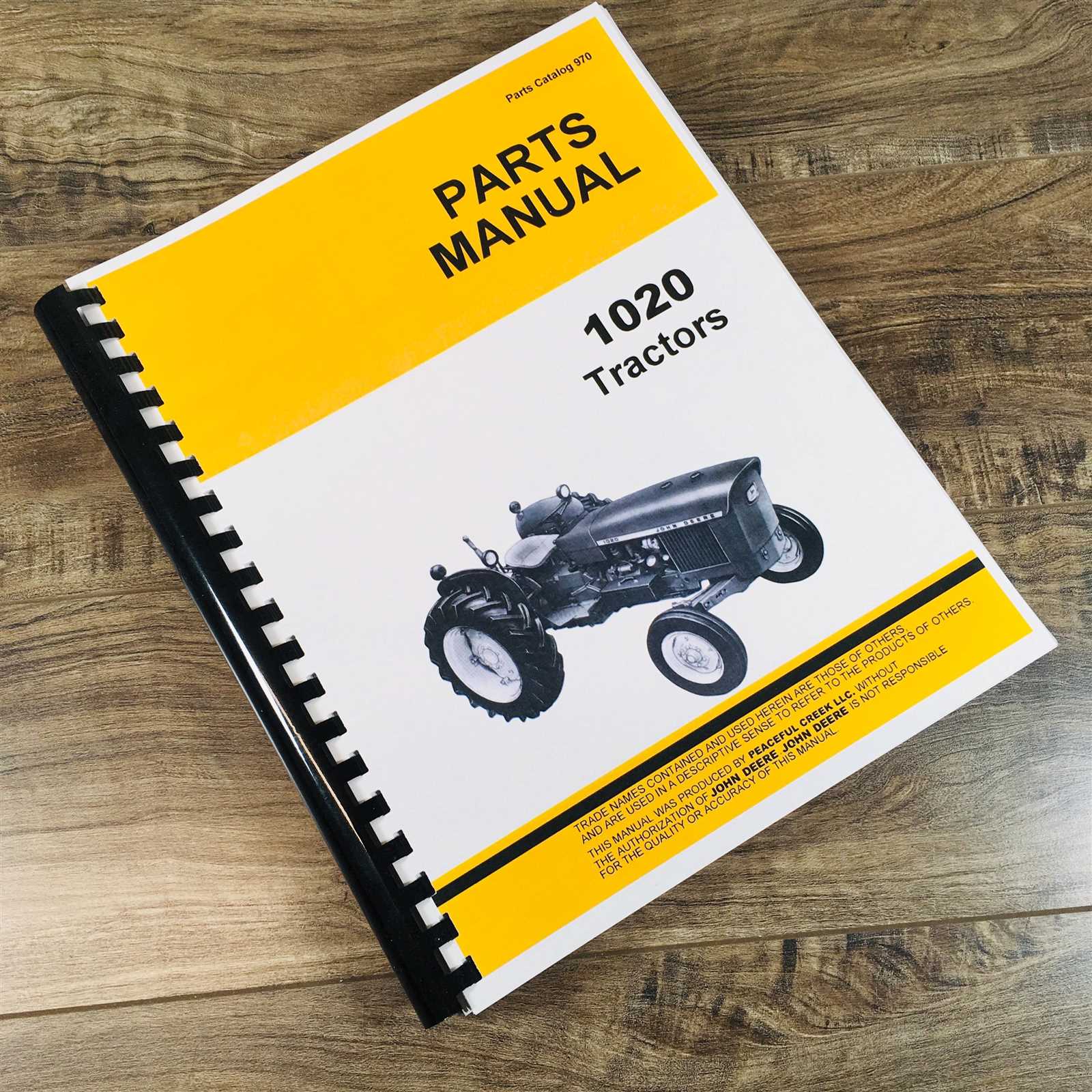
The functionality of any agricultural machine relies heavily on the design and performance of its key elements. Each section is built to contribute to the overall efficiency and effectiveness of the equipment, making it capable of handling various tasks. This section will focus on the most important components that ensure the tractor operates smoothly and efficiently.
At the heart of the vehicle lies the engine system, responsible for generating the power needed to drive all other functions. It is crucial to understand the engine’s structure and its connection to other parts, as any malfunction here can affect the entire performance. Alongside the engine, the fuel system ensures that the machinery receives the right amount of fuel to maintain optimal output.
Another essential component is the transmission system, which is responsible for controlling the speed and torque delivered to the wheels. This system ensures that the vehicle adapts to different work conditions, offering flexibility in various farming operations. Understanding the function of the transmission allows for smoother operation and easier troubleshooting.
Finally, the chassis forms the foundation of the entire structure, housing key components and providing stability. A solid chassis is necessary for handling heavy loads and ensuring the overall durability of the machine. Proper care and regular checks of these critical sections will keep the machine in working order for years to come.
How to Interpret the John Deere B Diagram
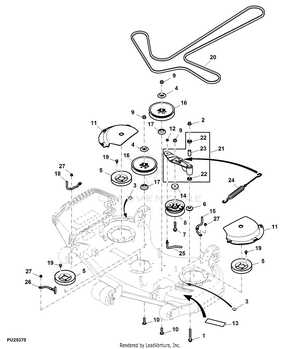
Understanding a schematic is an essential skill when it comes to maintaining and repairing complex machinery. A well-structured layout can provide a clear overview of how each component fits together and functions within the system. This section will guide you through the process of interpreting the diagram, ensuring you can identify the key components and understand their relationships.
Reading the Layout and Symbols
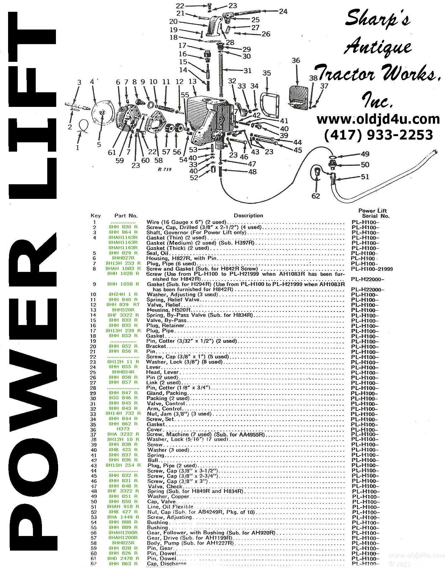
Most schematics use a set of standardized symbols to represent different parts of the equipment. These symbols are designed to simplify the understanding of complex systems. Familiarizing yourself with these symbols is the first step to making sense of the diagram. Each icon corresponds to a specific part, whether it’s mechanical, electrical, or structural, allowing you to pinpoint areas of interest easily.
Connecting Components and Systems
The next step is to understand how the components are interconnected. The diagram often shows lines that represent the flow of power, energy, or signals between parts. Following these lines will help you trace how one component influences another, whether it’s the transmission interacting with the engine or the electrical system powering the controls. Understanding these connections is vital for diagnosing issues and performing repairs efficiently.
Once you are comfortable with the symbols and connections, interpreting the layout becomes a straightforward task. This knowledge ensures that you can approach maintenance and troubleshooting with confidence, minimizing downtime and extending the lifespan of the equipment.