Having a clear understanding of the individual components of any machinery is essential for effective maintenance and repair. Whether you’re an experienced technician or a beginner, recognizing each element’s function allows for easier troubleshooting and part replacement. This knowledge can help you extend the lifespan of your equipment and ensure optimal performance during use.
Visual guides are often the best way to familiarize oneself with a machine’s layout. These resources allow you to identify the parts quickly and understand their relationships, making maintenance tasks more manageable. By using these reference materials, you gain the confidence needed to address any issues that may arise and ensure your machinery operates smoothly.
Equipped with a solid understanding of the individual elements and their connections, you can proceed with repairs more efficiently. Knowing how to interpret these guides can be a valuable skill, whether you’re performing routine checks or handling more complex issues.
Understanding the John Deere SB14 Components
To effectively maintain and repair any machine, it’s essential to first understand the different components that make up its structure. Each part plays a crucial role in the overall functioning, and recognizing their positions and interactions can simplify troubleshooting and replacement tasks. Familiarity with the assembly enables quicker identification of issues and contributes to a smoother maintenance process.
Machines are often designed with a clear arrangement of interconnected elements, each with a specific purpose. These parts work together to ensure that the equipment performs as intended, and even minor faults in one part can cause the entire system to malfunction. Having a comprehensive understanding of each component allows for more efficient repairs, as well as the ability to pinpoint problems more accurately.
In this section, we’ll explore the key components of the machinery, breaking down their individual functions and their relationship to one another. By understanding how each piece fits into the larger system, you can gain greater control over the maintenance and repair processes, ensuring your equipment remains in peak condition for years to come.
Identifying Key Parts in the Diagram
Recognizing the essential components of machinery is a fundamental step in both maintenance and repair. When you are provided with a visual representation of the equipment, it becomes much easier to identify each critical part and understand its role within the system. Knowing how to interpret these visuals enables you to make informed decisions, ensuring accurate diagnostics and effective solutions.
Commonly Highlighted Components

Visual guides often emphasize the most important elements that require frequent attention or maintenance. These parts may include major mechanical sections, control mechanisms, and other components integral to the machine’s operation. Understanding these highlighted sections allows you to focus your efforts where they are needed most, streamlining the process of identifying potential issues.
Connections and Relationships Between Parts
It’s not only about recognizing individual components but also understanding how they are interconnected. Each part’s function often depends on its relationship with others, making it vital to know how they interact. This knowledge helps prevent overlooking underlying issues that might arise from one part affecting the others, ensuring comprehensive maintenance.
How to Use the SB14 Parts Diagram for Repairs

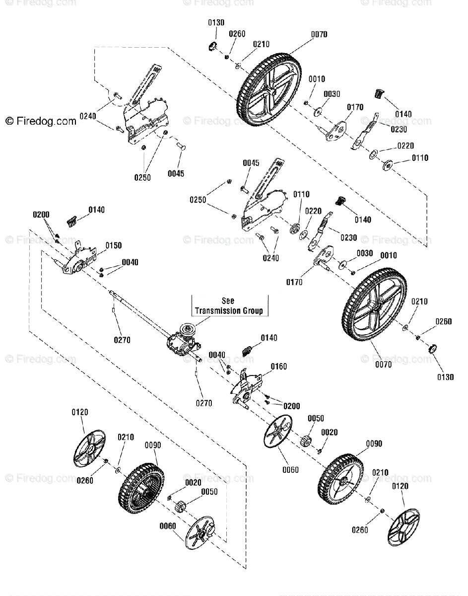
Effective repairs often begin with a thorough understanding of the machine’s components and how they are laid out. A visual guide can provide a clear representation of all relevant parts, helping you identify potential issues and efficiently replace or adjust elements. By following a structured approach, you can ensure that every aspect of the equipment is addressed correctly during the repair process.
Start by examining the diagram carefully to familiarize yourself with the overall structure. Pay attention to key components that are essential for the machine’s functionality, as these parts are often the ones that require the most maintenance. Once you’ve identified these critical elements, you can locate them in the actual equipment and assess their condition more effectively.
After pinpointing the necessary parts, use the guide to compare the existing components with the recommended specifications. This can help you identify any discrepancies, such as worn-out or broken parts that need replacement. By cross-referencing the visual representation with the real-life machine, you can make informed decisions and carry out precise repairs that restore the system to full working order.