Understanding the intricate structure of a complex machine is essential for proper maintenance and effective operation. A well-organized schematic provides users with a clear view of how each part contributes to the overall functionality, helping both owners and technicians during repairs or upgrades.
Identification of crucial components is fundamental when troubleshooting or replacing worn-out elements. Knowing the specific roles of various sections allows for more efficient service and prevents unnecessary downtime.
Having access to a comprehensive visual guide enhances users’ ability to handle machine issues independently, ensuring better performance and longevity. It also empowers individuals to identify potential concerns before they escalate into major problems.
Understanding the Key Components

Every machine is composed of various essential elements that work together to ensure smooth operation. These parts, though individually simple, serve specific functions that contribute to the overall efficiency and effectiveness of the system. Understanding how these components interact helps in performing better maintenance and diagnosing issues early on.
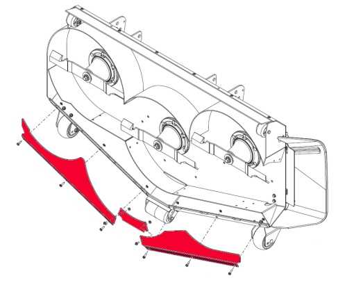
Familiarity with each section’s role allows users to quickly identify which part may need attention. Whether it’s the motor, frame, or other critical elements, knowing the function of each piece simplifies the repair process. A detailed understanding can also assist in determining the appropriate time for replacement or upgrades, ensuring long-term reliability.
The proper functioning of the system depends on how well the components are maintained and replaced when necessary. Regular inspection and knowledge of the individual parts enhance the machine’s performance and prevent breakdowns, making it more efficient for extended use.
How to Read the Schematic
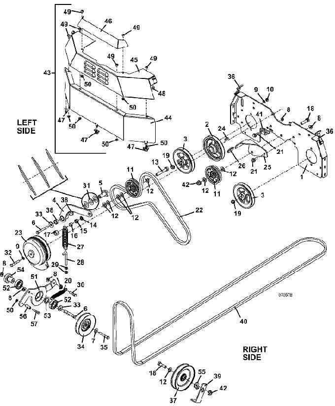
Interpreting a machine’s schematic is crucial for understanding the arrangement and function of its components. These visual representations provide a clear overview of how different parts are connected, helping users identify specific elements for maintenance or repair. Learning to read these diagrams accurately is a valuable skill for anyone involved in machine upkeep.
Identifying Key Elements
Each section of the schematic is typically labeled with reference numbers or codes, indicating where specific components fit within the system. Understanding these markings is essential for locating parts and ensuring accurate replacements or adjustments. It’s important to familiarize yourself with the various symbols used, as they represent different types of parts or mechanisms.
Following the Connections
The lines or arrows on the schematic indicate how the components interact with one another. By following these connections, you can trace the flow of energy, power, or materials throughout the system. This knowledge helps in troubleshooting and understanding how the machine operates as a whole.
Common Replacement Components

Over time, certain components of any machine may wear down and require replacement. Identifying which elements need attention ensures that the equipment continues to function at peak performance. This section highlights the most commonly replaced components that often need servicing or upgrading.
Engine and Drive System Elements
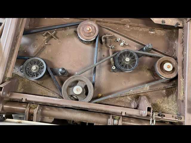
One of the most frequently replaced components involves the engine and associated drive systems. Parts such as belts, pulleys, and the engine itself can degrade with heavy use. These elements are crucial for the overall operation, and timely replacement prevents disruptions in performance.
Hydraulic and Electrical Components
Hydraulic systems and electrical components are also key to ensuring smooth functionality. Hoses, seals, and wiring can experience wear and tear, especially with extensive use. Keeping an eye on these components can prevent leaks, electrical issues, or system failures.