When working with intricate machinery, understanding the layout of its individual components is crucial. A clear visual representation of the system’s parts allows technicians and enthusiasts to identify and assemble them correctly, ensuring smooth functionality. This guide offers a detailed look at the structure of a particular model, breaking down its essential elements and highlighting their roles within the entire setup.
Efficient maintenance relies on having a clear reference for each part’s position and connection. With an intuitive overview, any repairs or adjustments become simpler, reducing the risk of errors. This comprehensive breakdown enables users to locate specific components with ease, whether for troubleshooting or routine upkeep.
Understanding how each element interacts with others enhances both performance and longevity. This guide serves as an invaluable tool, aiding in the precise handling and upkeep of the system. By studying its schematic, users can better appreciate the importance of each part, fostering a deeper knowledge of the overall machinery.
Understanding the Assembly Layout

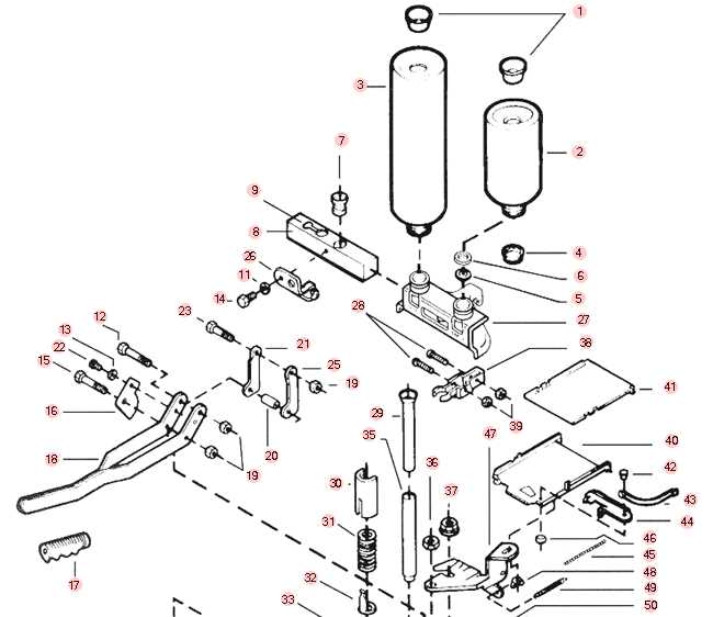
Grasping the overall arrangement of a machine’s components is essential for both assembly and maintenance. A well-organized layout provides clarity on the location and interaction of each individual element within the system. By breaking down the configuration, users can better understand how each part contributes to the overall performance.
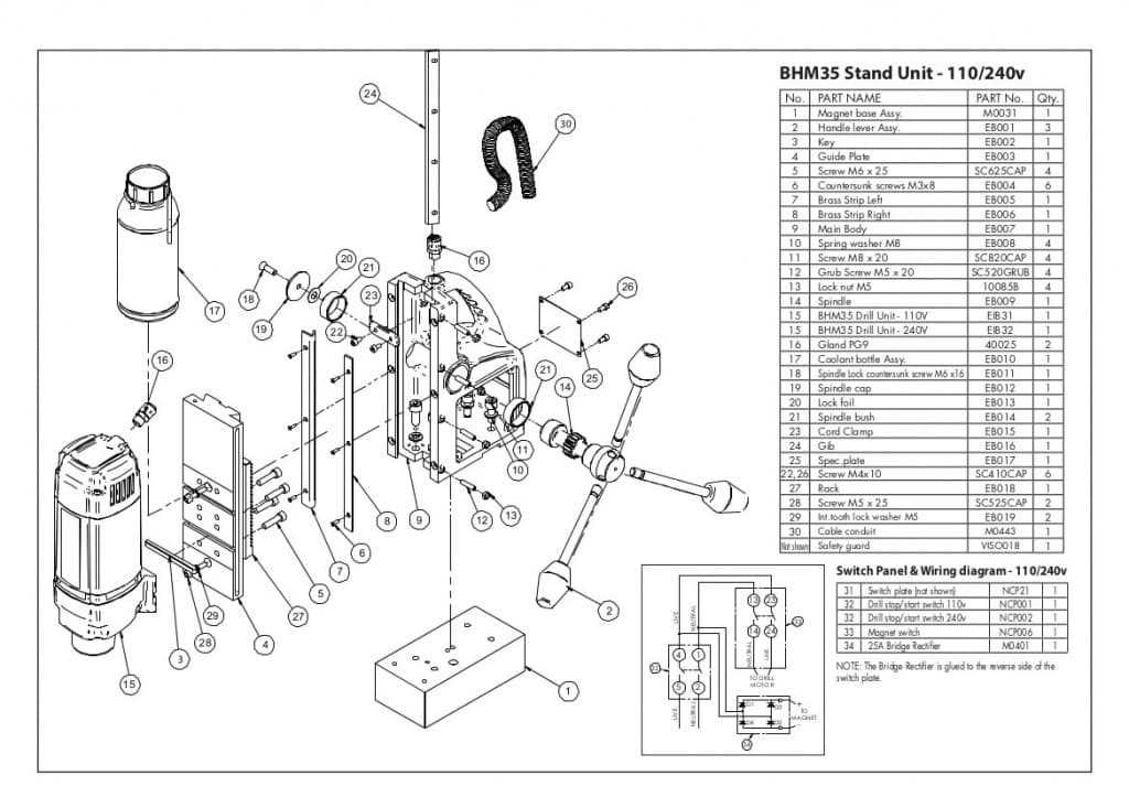
The layout often includes a detailed representation of various parts, showing their relationships and positions in the machine. This visual guide serves as a roadmap for anyone working with the equipment, allowing them to quickly identify components and troubleshoot any issues that may arise. By understanding this arrangement, operators can achieve more efficient and effective use of the system.
Familiarity with the entire structure also facilitates smoother repair and replacement processes. Knowing the exact placement of each component ensures that all necessary steps are taken during maintenance. This knowledge is critical in preventing mistakes and ensuring the machine continues to operate at optimal levels.
Exploring Key Components of the Machine

Every complex system is made up of several crucial elements that work together to ensure smooth operation. Understanding these key components is vital for anyone who works with the equipment. By examining each part closely, users can identify its function and how it contributes to the overall performance of the machine.
Some of the primary elements include the drive mechanisms, control systems, and safety features. These parts play an essential role in the operation, controlling everything from motion to stability. Each component is carefully designed to fit within the broader assembly, ensuring maximum efficiency and reliability.
Familiarizing yourself with these parts enables quicker troubleshooting, repairs, and upgrades. Recognizing how each piece interacts with others allows for a more precise diagnosis when problems arise. With this knowledge, maintenance becomes easier, and the system can continue functioning optimally for a longer period of time.
How to Use the Assembly Layout Effectively
Having a detailed visual reference of a system’s components is invaluable when working on maintenance, repairs, or upgrades. Understanding how to interpret this reference correctly ensures that every element is identified and handled properly, improving the accuracy and efficiency of the task at hand. This section will explore how to use this resource to its fullest potential.
Understanding the Key Features

Before diving into the layout, it’s important to familiarize yourself with the key features of the illustration. These typically include labels, part numbers, and arrows showing the connections between elements. By understanding these notations, you can quickly pinpoint the specific part you need to focus on. Clear comprehension of the layout’s structure ensures that you don’t waste time searching for the wrong components.
Applying the Layout for Troubleshooting and Maintenance
Once you are familiar with the layout, it becomes a powerful tool for troubleshooting. By matching symptoms with specific components, you can identify which part may be malfunctioning. Additionally, using this guide during maintenance allows you to perform checks systematically, ensuring no critical element is overlooked. With a clear view of how everything fits together, proper care and replacement become much more manageable.