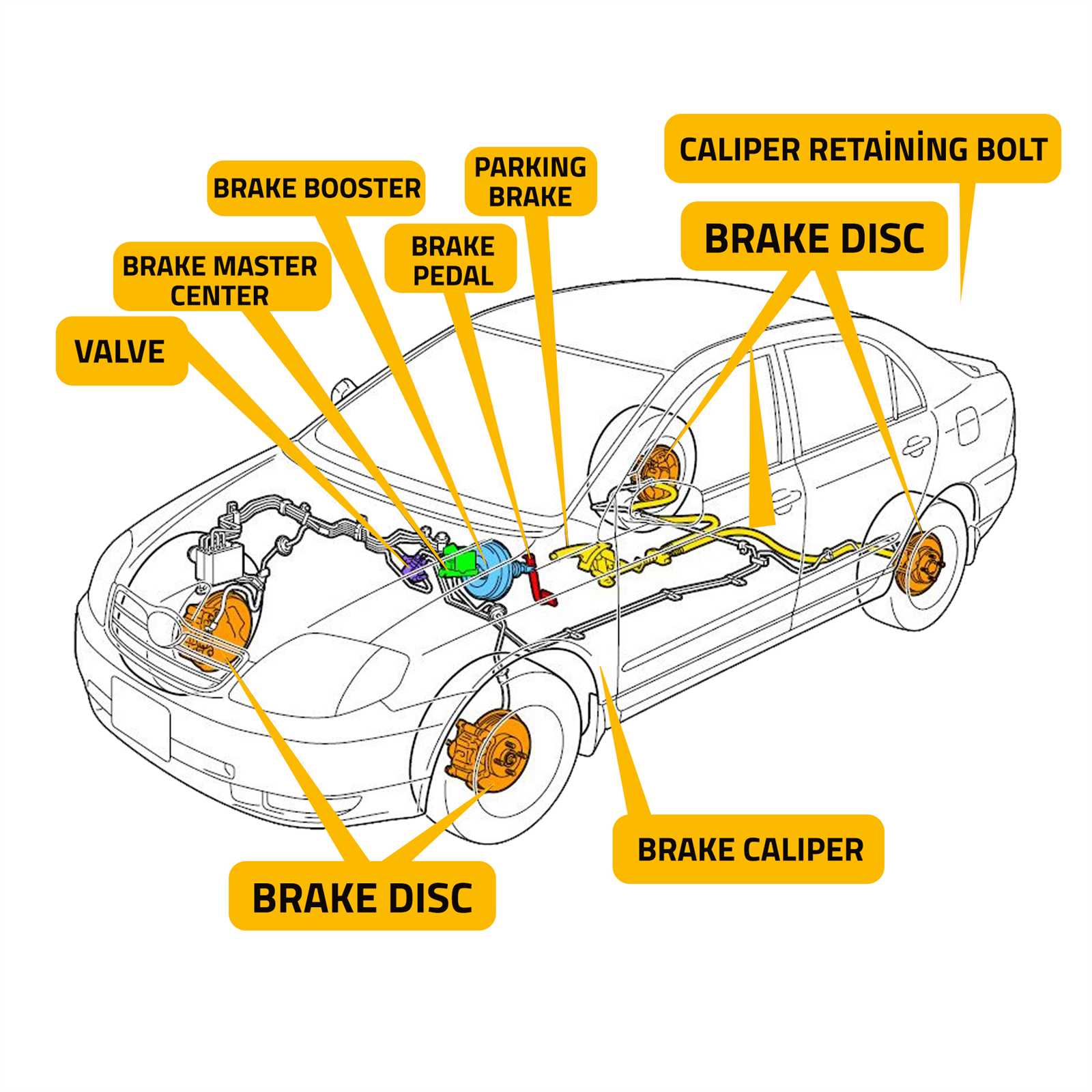
Modern vehicles rely on complex mechanisms to ensure smooth operation, particularly when it comes to enhancing the driver’s ability to control stopping power. These systems use a series of interconnected elements that function together to improve overall performance. Understanding how each component contributes to this process is essential for both vehicle maintenance and repair.
In any automotive stopping mechanism, precise interaction between different elements is key to achieving the desired effect. Each component plays a vital role, from regulating pressure to ensuring the proper response when the pedal is engaged. A deeper look into these mechanisms provides valuable insights for anyone looking to understand the technology behind vehicle control systems.
Whether you’re a mechanic or a car enthusiast, gaining familiarity with these systems helps in diagnosing issues and performing necessary maintenance. Proper knowledge of these components allows for better handling of malfunctions and supports efforts to maintain vehicle safety and efficiency. With an understanding of how each part functions, you can ensure your car remains in top condition.
Understanding Brake Booster Components

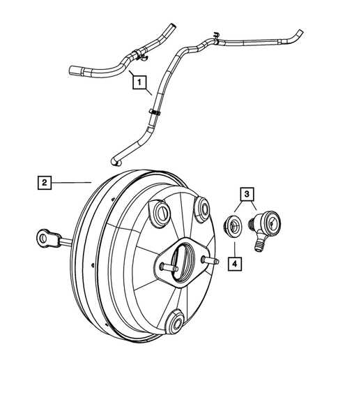
To fully grasp the function of the system that assists with vehicle stopping power, it’s important to understand how its individual elements work together. These components ensure that the force applied to the pedal is enhanced, making it easier for the driver to stop the vehicle effectively. Without the proper interaction between these pieces, the overall performance of the stopping mechanism would be compromised.
The Role of Each Component
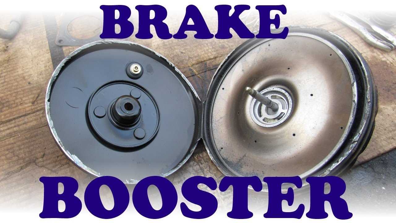
Each part plays a distinct role in facilitating the desired outcome. The primary function of the system is to amplify the force exerted on the pedal, allowing for more effective braking with less physical effort. Key components include valves, diaphragms, and chambers that regulate pressure and airflow, all contributing to smoother, more responsive control when stopping.
Common Components and Their Functions
Among the most crucial elements in this system are the vacuum pump, diaphragm, and master cylinder. The vacuum pump generates the necessary pressure for the mechanism to function, while the diaphragm works by transferring the force. The master cylinder is the point at which the driver’s input is converted into mechanical force, controlling the flow of hydraulic fluid and ultimately applying the brakes.
How Brake Booster Parts Work Together
The efficiency of a vehicle’s stopping system relies on the precise coordination of multiple components that work in unison. These elements combine to enhance the driver’s ability to apply the correct force with minimal effort. When engaged, the system amplifies the pressure applied to the braking mechanism, ensuring smoother and more responsive stops.
Cooperation Between Components
Each component interacts to create the necessary force needed to activate the vehicle’s stopping system. When the driver presses the pedal, a vacuum or hydraulic system comes into play, generating the necessary pressure. This pressure then travels through interconnected elements, activating the master cylinder, which controls the flow of fluid to the braking components.
Pressure Regulation and Amplification
One of the critical functions of this system is its ability to regulate and amplify pressure. The diaphragm, valves, and chambers work together to manage airflow and pressure levels. As the driver applies pressure, these components adjust the force, ensuring that only the required amount reaches the braking system, allowing for consistent and reliable performance.
Common Issues in Brake Booster Systems
Over time, several problems can arise within the system that amplifies the force applied when stopping a vehicle. These issues can lead to a significant decrease in performance, making it harder for the driver to exert the necessary force on the pedal. Identifying and addressing these problems is crucial for maintaining the system’s efficiency and ensuring overall safety.
Common Malfunctions
Several malfunctions can cause the system to fail or operate inefficiently. The most frequent issues include:
- Vacuum Leaks: Loss of pressure due to a compromised vacuum seal can prevent the system from functioning properly.
- Damaged Diaphragm: A torn or weakened diaphragm may disrupt the pressure amplification process, affecting responsiveness.
- Faulty Valves: Malfunctioning valves can cause inconsistent pressure regulation, leading to uneven braking performance.
- Clogged Air Filters: Blocked filters can restrict airflow, reducing the efficiency of the system and making it harder to stop the vehicle.
Signs of Malfunction

If the system is malfunctioning, the driver may experience a variety of symptoms, such as:
- Hard Pedal: Difficulty pressing the pedal with normal force is a common sign of a malfunctioning system.
- Increased Stopping Distance: If the system is not amplifying pressure properly, stopping distances may lengthen.
- Unusual Sounds: Hissing or other abnormal noises can indicate air leaks or other internal issues.