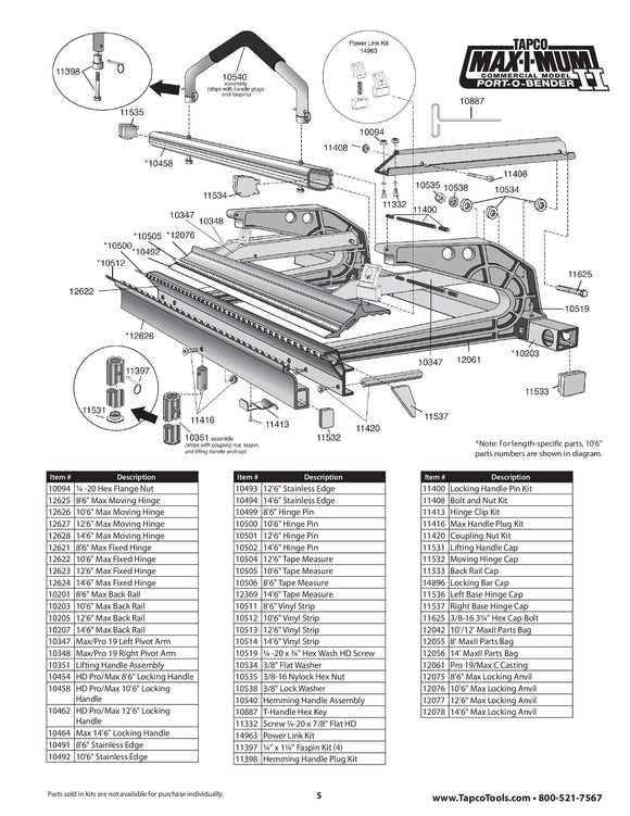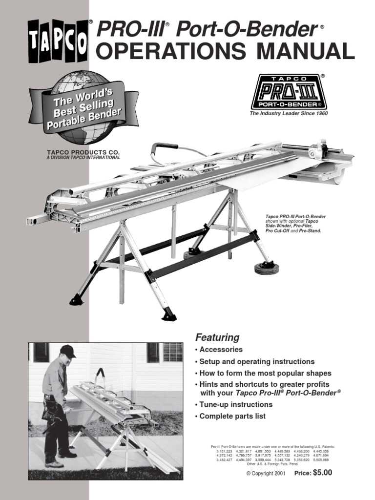
Accurate schematics play a crucial role in the repair and maintenance of complex machinery. These detailed visual guides are essential for identifying individual components and their connections, ensuring a smoother workflow during fixes and upgrades. By examining these visual representations, users can gain a deeper understanding of how various elements work together within a larger system.
Effective utilization of these guides is key to ensuring the longevity and functionality of equipment. Having a clear reference for each piece allows technicians to quickly locate issues and implement proper solutions. A well-detailed map simplifies troubleshooting, making the repair process faster and more efficient.
As systems evolve and become more intricate, the need for precise and comprehensive charts becomes even more important. Without these detailed visual aids, performing maintenance tasks could be time-consuming and prone to errors. Familiarizing oneself with these layouts ensures both accuracy and consistency in any repair operation.
Understanding System Layout for Efficient Maintenance

Properly structured visual guides are fundamental to understanding the configuration of key components within a system. These layouts provide a clear representation of how various elements are connected and interact with each other. By studying these schematics, users can familiarize themselves with the specific arrangement, making it easier to identify and address any issues that may arise during maintenance.
Each system diagram offers a comprehensive overview, showing the positioning and function of individual units within the machinery. The clarity of these charts ensures that operators can easily locate the relevant sections, enhancing their ability to troubleshoot or replace malfunctioning components. A well-constructed layout is designed to minimize confusion and streamline the repair process.
To optimize system performance, understanding the physical layout is just as important as knowing the technical specifications. This knowledge allows for more effective interventions and ensures that any adjustments or repairs are performed with precision. With the right approach, these visual tools become an indispensable asset for efficient operation and long-term reliability.
Comprehensive Guide to Component Identification
Recognizing and understanding the different elements within a mechanical system is crucial for efficient maintenance and repair. A comprehensive guide provides an in-depth look at each part, helping users easily identify the components and their specific functions. Mastery of this knowledge ensures that maintenance tasks can be performed with accuracy, avoiding unnecessary errors and delays.
Each element within the system has a distinct role, and understanding its place in the overall configuration is key to efficient troubleshooting. Identifying these components correctly allows for quicker diagnosis of issues and more precise repairs. Detailed visual aids, paired with clear labeling, help to ensure that no part is overlooked during inspection or maintenance procedures.
By following a systematic approach to identification, operators can gain confidence in their ability to manage complex systems. This knowledge not only improves repair efficiency but also contributes to the long-term performance and reliability of the machinery. Familiarity with each component empowers users to make informed decisions, whether performing routine checks or addressing more significant problems.
How to Read Technical Schematics Effectively
Understanding technical charts and visual layouts is essential for anyone involved in the maintenance or repair of mechanical systems. These visual representations provide a detailed view of the system, but interpreting them correctly requires focus and familiarity with specific symbols and notations. By learning to read these charts effectively, users can quickly identify components and connections, making the troubleshooting process more efficient.
Here are key steps to help you read technical layouts with ease:
- Familiarize Yourself with the Symbols: Each system uses a set of standardized symbols to represent various components. Knowing these symbols is the first step in interpreting any schematic.
- Understand the Layout Structure: Most charts are organized in a logical flow, with components placed in a way that reflects their position within the actual system. Look for the overall structure before focusing on individual parts.
- Pay Attention to Labels: Clear labeling of each component is essential for easy identification. Be sure to check for part names and numbers, as well as connection points.
- Follow the Connections: Understand how different elements are interconnected. Trace the lines or arrows that show the flow of operation or signal within the system.
By applying these techniques, you can quickly gain a solid understanding of any technical layout, enabling more efficient maintenance and repair work. Over time, familiarity with these visual tools will make interpreting complex schematics a faster and more intuitive task.
Step-by-Step Breakdown for Maintenance
Performing maintenance on complex systems requires a structured approach to ensure that each task is completed correctly and efficiently. By following a detailed, step-by-step guide, technicians can ensure that no critical steps are overlooked, and the system continues to function optimally. This methodical process not only aids in resolving immediate issues but also helps to extend the overall lifespan of the equipment.
Preparation and Safety Checks
The first step in any maintenance procedure is to prepare the work area and ensure all necessary tools and components are available. Safety should always be a priority, so make sure that protective equipment is worn and that the system is safely powered down before beginning any work. Proper preparation reduces the risk of accidents and ensures that the process goes smoothly.
System Inspection and Diagnosis
Once the area is prepared, the next step is to perform a thorough inspection of the system. Carefully examine each component and check for any signs of wear, damage, or malfunction. Use the available charts or guides to identify parts that may require attention. Diagnosing the issue accurately is crucial for selecting the right solutions and avoiding unnecessary replacements.
By breaking down the maintenance procedure into these key stages, technicians can approach the task with greater confidence and efficiency. This approach minimizes errors and ensures that the system remains in optimal working condition for longer periods.
Importance of Accurate System Schematics
Precise and well-detailed schematics are essential for any maintenance or repair task involving complex machinery. These visual guides provide a clear, comprehensive overview of a system, highlighting the critical connections and components that are crucial for its operation. Without accurate schematics, diagnosing problems and carrying out effective repairs becomes a challenging task, often leading to inefficiencies or errors.
Streamlining Troubleshooting and Repairs

Accurate visual guides simplify the troubleshooting process by allowing technicians to quickly locate the issue. With a well-structured schematic, it’s easier to identify faulty components, misalignments, or wear and tear that could hinder the system’s performance. Clear representations enable faster and more efficient repairs, reducing downtime and improving overall system reliability.
Enhancing System Longevity and Performance
Having a detailed, correct schematic also contributes to the long-term performance of the system. Regular maintenance based on accurate diagrams ensures that components are properly maintained, preventing premature failure. Moreover, understanding the layout of the system allows for more informed decisions when making upgrades or replacements, further extending the life of the equipment.
| Component | Potential Issue | Solution |
|---|---|---|
| Component A | Wear and Tear | Replace with Correct Part |
| Component B | Misalignment | Realign Using Diagram Instructions |
| Component C | Damage | Consult Schematic for Replacement |
In conclusion, the importance of accurate schematics cannot be overstated. They not only enhance repair efficiency but also contribute significantly to the reliability and longevity of the system.